
US 188
UNITED STATES PATENT OFFICE.
IMPROVEMENT IN MANY-CHAMBERED-CYLINDER FIRE-ARMS.
Specification forming part of Letters Patent No. 188, dated April 28, 1837.
To all whom it may concern:
Be it known that I, John W. Cochran, of the city of New York, in the State of New York, have invented certain Improvements in the Manner of Constructing Fire-Arms— such as Rifles, Pistols, and other fire-arms of a like kind; and I do hereby declare that the following is a full and exact description thereof.
I denominate this kind of fire-arm the “many-chambered non-recoil firearm.” It is called “many chambered” from its being so constructed as to contain a number of chambers in one cylinder, which cylinder is made to revolve upon its axis, so as to bring the respective chambers successively to coincide with the bore of the fire-arm, in consequence of which they may, after being properly charged, be discharged in rapid succession by means to be presently explained.
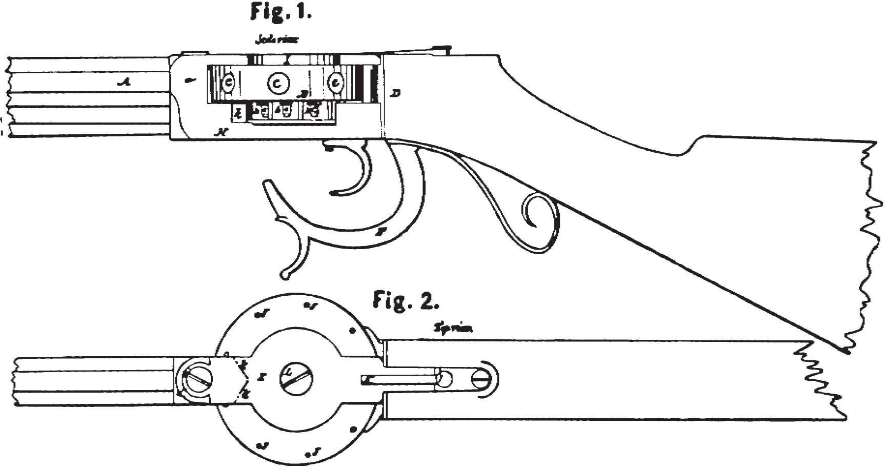
In the accompanying drawings, A represents the end of the barrel toward the stock. B B is the cylinder, and C C the openings into the respective chambers. His what I denominate the “lower stock-strap,” and I the upper stock-strap. The part a of the lower stock-strap is in one piece with the part H, and into this part a the barrel A is screwed, its end passing through the part a and fitting as closely against the cylinder B as possible, so as to allow of its revolving freely. The end of the barrel next the cylinder is made concave, so as to fit the cylinder. The understock-strap extends along and is let into the under side of the stock, being screwed thereto in the usual manner.
I generally form nine chambers in the cylinder; but the number of these may vary, an odd number, however, being preferred, as the catch-holes J on the face of the cylinder may then be conveniently, made in the solid part of the cylinder, between the chambers. In a rifle the cylinder is usually made about three and a half inches in diameter, or from seven to eight diameters of the ball, and three-fourths of an inch thick. The chambers are bored in conically, in a direct line from the periphery toward the axis, to a depth equal to about three diameters of the ball, more or less. They are of the full diameter of the bore of the barrel at their mouths, and about one-eighth of an inch in diameter at their lower ends. The upper stock strap, I, is at its fore end, i, let into and screwed to the rising piece a of the under stock-strap, and is in like manner screwed to the stock at its opposite end, thus leaving a space of sufficient.length and depth to receive the cylinder and the tubes or nipples which are attached to it, for the purpose of affixing the percussion-caps. These tubes or nipples are seen at e e e, Figure 1, in the accompanying drawings. They are screwed into holes drilled through the lower side of the cylinder into each chamber, near its frustral termination or inner end.
To defend the caps from accidental injury after they are placed on the nipples, they are received within the periphery of what I call the “percussion-cap guard.” This consists of wheel of brass or other metal, b b, Fig. 1, attached concentrically on the lower side of the cylinder, being about two inches in diameter, and of a thickness sufficient to receive the caps. The lower face of this cap-guard is shown in Fig. 3, exhibiting the manner in which its periphery is scalloped or notched, so as partially to surround the cap. A thin circular plate, Fig. 4 is placed immediately under the cap-guard, and may, in fact, be said to make apart of it. It removes all danger of the falling off of the caps, and otherwise protects them. It has a scallop at d, to allow of the placing the caps upon the nipples, and a hole through it at if corresponding with a hole through the under stock-strap, to admit the point of the hammer to strike upon the cap. The recess in the under stock-strap, which receives the percussion guard and caps, is filed out, so as to form an angle close to the wheel, in the form shown by dotted lines k k, Fig. 2, to allow of the free escape of the smoke and fire from explosion of the cap. The dark part k, Fig. 1, shows this opening on one side. A screw, the head of which is seen at L, passes through the upper and screws into the under stock-strap, and forms the axis upon which the cylinder revolves. The under stock-strap is thickened on its upper side by leaving a cylindrical stump on it, which is received in the opening gin the cap-guard, thus allowing a deep hole for the reception of the screw, and giving it stability as the axis of the cylinder.
J J J are catch-holes, into which the point of a spring catch or pawl, K, falls, and which may be raised by the pressure of the thumb.
The lock which I use is one of the utmost simplicity of construction. F is the hammer, shown in the position it assumes when cocked. It has a simple mainspring, which passes along and is attached to that part of the under stock-strap which extends back under the stock. When cocked the tumbler end of the hammer is caught by the trigger, and when disengaged the opposite end strikes the cap. The manner in which I arrange the respective parts of my lock are shown distinctly in Fig. 5. In small-arms— such as pistols— the trigger may be placed behind the hammer, as shown in Fig. 6.
What I claim as my invention in the within described many-chambered fire-arm is—
1. The combination of a many-chambered cylinder, the chambers in which are formed around its periphery in the way herein described, with a rifle, pistol, carbine, or other barrel, and combined also with the stock of such fire-arm by means of the stock-straps, constructed substantially in the manner set forth.
2. The combining of the percussion-cap guard, together with the thin circular plate under it, with a cylinder constructed and connected, as above set forth, for the protection of the percussion-caps.
3. The manner of connecting the barrel in arms so constructed with the rising piece a of the under stock-strap by screwing it therein, the whole combined so as to constitute a fire-arm substantially the same with the foregoing.
JOHN W. COCHRAN.
Witnesses:
Thos. P. Jones,
W. Thompson.