
US 640070
UNITED STATES PATENT OFFICE.
JACOB GOTTFRIED AESCHBACHER, OF ROSARIO, ARGENTINA.
FIREARM.
SPECIFICATION forming part of Letters Patent No. 640,070, dated December 26, 1899. Application filed May 15, 1899. Serial No. 716,893. (No model.)
To all whom it may concern:
Be it known that I, JACOB GOTTFRIED AESCHBACHER, of Rosario de Santa Fé, Argentina, have invented a new and useful Improvement in Firearms, of which the following is a fall, clear, and exact description.
One object of the invention is to provide attachments capable of being quickly and conveniently applied to any revolver or other firearm, which attachments will enable a marksman to use a cartridge of small caliber in a revolver or arm constructed to carry a cartridge of large caliber, thereby not only economizing in ammunition, but reducing the noise of the explosion and enabling a marksman to become familiar with a certain weapon and practice in places which would otherwise not be available.
A further object of the invention is to so construct the attachments that said attachments will not necessitate the alteration of the weapons to which they are to be applied, and, furthermore, to so construct the attachments as to insure accuracy of fire.
Another object of the invention is to provide a means for using the attachments in connection with either rim or center fire cartridges.
The invention consists in the novel construction and combination of the several parts, as will be hereinafter fully set forth, and pointed out in the claims.
Reference is to be had to the accompanying drawings, forming a part of this specification, in which similar characters of reference indicate corresponding parts in all the figures.
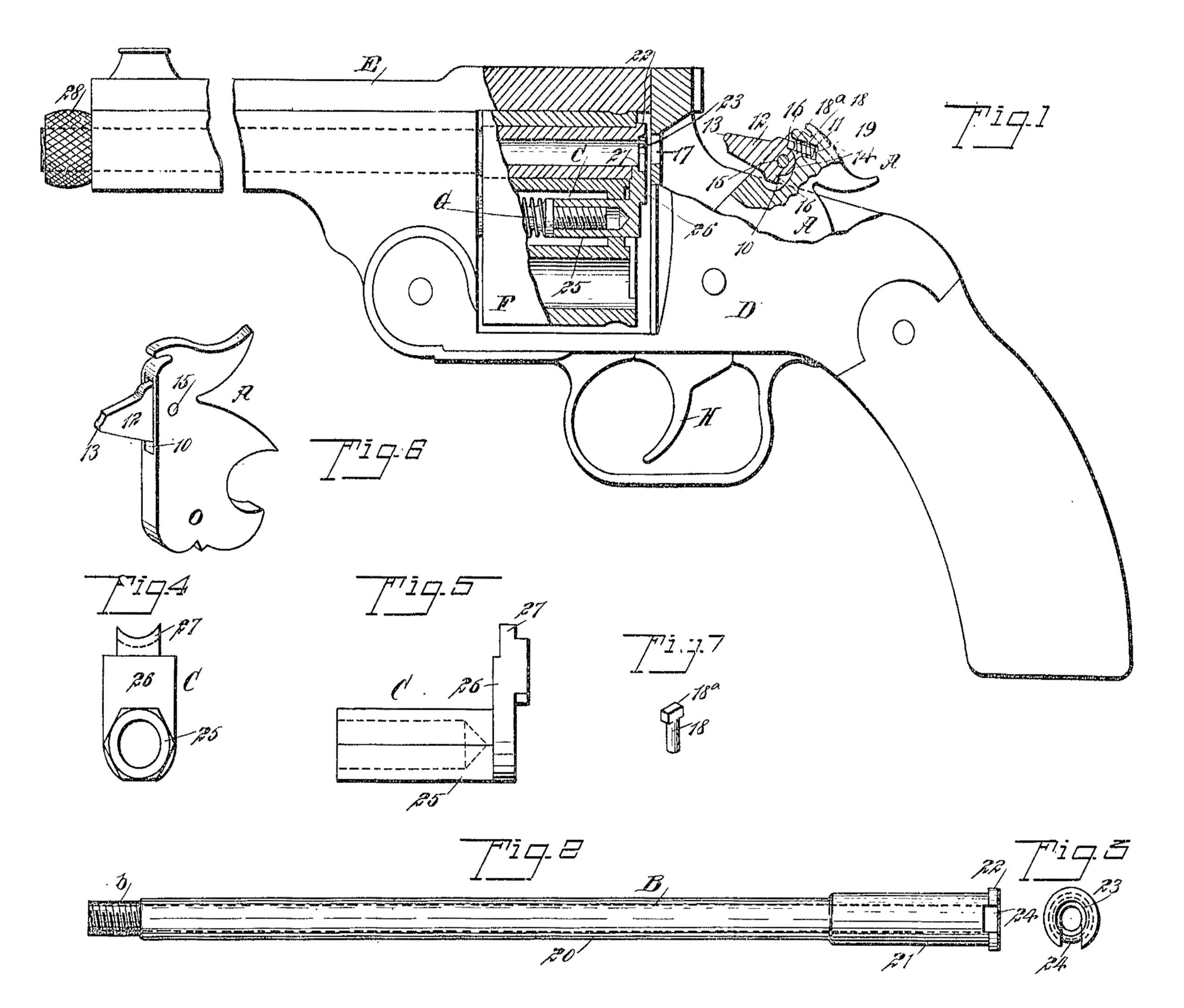
Figure 1 is a side view of a revolver, parts thereof being broken away, illustrating the application of the attachments thereto, a portion of the hammer being in section. Fig. 2 is a bottom plan view of the auxiliary barrel employed. Fig. 3 is a rear end view of the said auxiliary barrel when in place in the firearm. Fig. 4 is a front elevation of the ejector employed. Fig. 5 is a side elevation of the said ejector. Fig. 6 is a perspective view of the hammer, and Fig. 7 is a detail perspective view of a stop used in connection with the firing-pin of the hammer.
A represents the hammer of the attachment, B the barrel, and C the ejector.
D represents the body of a revolver of the Smith & Wesson type or that type of revolver that is broken for loading and for the ejection of the shell.
G represents the ejector-stem; E, the barrel of the revolver; F, the cylinder, and H the trigger.
The hammer A, that is adapted to be substituted for the hammer belonging to the firearm, is provided at the upper portion of its front face with a recess 10, the rear wall whereof is usually concaved, as shown in Fig. 1, and at the upper portion of the rear wail of the recess 10 a cavity 11 is produced. This recess is adapted to receive the firing-pin 12. The forward end of the striking-pin is more or less beveled, so as to form a striking-point 13 at one side of the center of said pin, and the firing-pin is centrally pivoted at its rear in the said recess 10 by means of a suitable pin 15. The rear central portion of the firing-pin is preferably cylindrical, as shown in Fig. 1, and a rearwardly-facing shoulder 16 is formed at the side of the pivot of said pin, so that said pin when in one position may be used upon center-fire cartridges and upon being reversed can be used with equally good results upon rim-fire cartridges. The firing-pin is held in proper position to enter the opening 17 in the frame of the weapon and strike the cartridge at a proper point by directing the firing-pin through the medium of a stud 18, provided with a head 18a, as shown in Fig. 7, which head has bearing against the uppermost shoulder 16 of the firing-pin, as shown in Fig. 1, and the body of the stud enters the cavity 11 in the hammer and is encircled by a spring 19, having beatings against the head 18a and the rear wall of said cavity 19.
The barrel B consists of a body-section 20, that is slightly longer than the length of the main barrel E of the weapon, and a rear section 21, that is adapted to enter a chamber in the cylinder F of the weapon. The outside diameter of the body portion of the auxiliary barrel B corresponds to the inner diameter of a chamber in the cylinder F, and the bore of the auxiliary barrel throughout its length is suitably rifled and is of a diameter to properly receive a bullet of small caliber—as, for example, caliber 22. The auxiliary barrel B is provided with a flange 22 at its rear end, and the said rear end portion at the flange is provided with a suitable depression 23, adapted to receive the rim of a cartridge to be loaded into the auxiliary barrel. In the bottom portion of said auxiliary barrel, at the flange 22, a recess 24 is made, adapted to receive the ejecting-finger of the ejector C.
The ejector C consists of a body 25, having a suitable bore adapted to be received by and attached to the ejector-spindle G when the ordinary ejector has been removed. The ejector C further consists of an upright section 26 at one end of the body, the upright section 26 terminating in a finger 27, adapted to enter the slot 24 at the rear of the barrel and engage with the forward face of the rim of a cartridge.
To accommodate the attachment to the requirements of a revolver of the type shown, the hammer A is substituted for.tiie ordinary hammer, or the said hammer A may be actually the hammer of the revolver, as said hammer A can be used upon any weapon to as great advantage as the ordinary hammer; but in either event the cylinder and ejector are removed from the revolver and the new ejector is placed upon the ejector-spindle G. After this has been accomplished the cylinder is again placed in position in the body. The auxiliary barrel B is now pushed into the cylinder and through the main barrel E, the slot 24 at the rear of the auxiliary barrel facing downward or in direction of the center of the cylinder. The ejector is then cocked and is permitted to spring into the said slot 24 in the rim of the auxiliary barrel. The flange 22 of the said auxiliary barrel will be thus close against the rear end of the main barrel, and in order to hold the auxiliary barrel firmly in place a nut 28 is screwed upon the outer end b of the auxiliary barrel, which end is reduced and exteriorly threaded, and if the hammer A is one that is provided with a recess 10 and channel 11 the firing-pin 12 is fitted into the said hammer. When these changes and additions have been made to a revolver, for example, a person may practice with a revolver of the desired weight, and at the same time a small-caliber cartridge only need be used in such work. The loading is very rapidly accomplished, since the cartridge is placed directly in the auxiliary barrel from the rear, and as the barrel is continuous the weapon must of necessity fire straight.
Having thus described my invention, I claim as new and desire to secure by Letters Patent—
1. A caliber-reducing attachment for firearms comprising an auxiliary barrel having a body-section adapted to fit within the main 60 barrel and a rear section adapted to fit within a chamber of the cylinder carried by the weapon, the said auxiliary barrel being provided with an opening at its rear end for the admission of the ejecting-finger of an ejector, the body-section of the auxiliary barrel being slightly longer than the main barrel of the weapon and projecting therefrom, and a nut screwing on the projecting end of the auxiliary barrel to lock said barrel in place in the weapon, substantially as described.
2. In a caliber-reducing attachment for fire-arms, an auxiliary barrel having one section of an exterior diameter corresponding to the interior diameter of the main barrel into which it is fitted, and a second section of an exterior diameter corresponding to the inner diameter of the chamber of a cylinder carried by the weapon, the bore of the auxiliary barrel being constant throughout, and a flange formed upon thé rear end of the said barrel, having an opening therein communicating with the bore and adapted to receive a portion of the ejector, for the purpose specified.
3. In a caliber-reducing attachment for fire-arms, a hammer having a recess in its front face, a reversible firing-pin having its rear end arranged in the recess, the said firing-pin extending beyond the front face of the hammer and the forward end of the said pin being beveled to form a striking-point at one side of the center of the firing-pin, a pin extending transversely through the rear end of the firing-pin and pivoting the firing-pin in the recess in the hammer, and a spring-pressed stud engaging the rear end of said firing-pin at one side of the pivot-pin, for the purpose set forth.
4. In a caliber-reducing attachment for fire-arms, a hammer provided with a recess in its front face having its rear wail concaved and a cavity at the upper portion of the rear wail of the recess, a firing-pin provided with a striking-point near one side, the said firing-pin having its rear end curved and terminating in a shoulder at the top and the bottom a pin extending through the rear end of the firing-pin between the shoulders and pivoting said firing-pin in the recess in the hammer and a stud held in the cavity in the hammer and having a head adapted to bear against the uppermost shoulder of the firing-pin, for the purpose set forth.
5. The combination, with the main barrel, cylinder and ejector-spindle of a revolver, of an auxiliary barrel having a constant inner bore, its exterior being in sections of different diameters, the exterior diameter of one section corresponding to the interior diameter of the barrel of the weapon, and the exterior diameter of the other section corresponding to the interior diameter of the chamber of the cylinder, said barrel being provided with a flange at its rear and with a depression to receive the rim of a cartridge, the auxiliary barrel at its rear being likewise provided with an opening leading into said depressions, an ejector adapted for attachment to the ejector-spindle of the weapon and having one section. arranged to enter the opening at the rear of the auxiliary barrel, and means for locking the auxiliary barrel in place in the weapon, as described.
6. The combination, with the main barrel, cylinder and ejector-spindle of a revolver, of an auxiliary barrel having a constant bore, its, exterior being in sections of different diameters, the exterior diameter of one section corresponding to the interior diameter of the barrel of the weapon, and the exterior diameter of the other section corresponding to the interior diameter of the chamber of the cylinder, said barrel being provided with a flange at its rear and with a depression to receive the rim of a cartridge, the auxiliary barrel at its rear being likewise provided with an opening leading into said depression, an ejector adapted for attachment to the ejector-spindle of the weapon and having one section arranged to enter the opening at the rear of the auxiliary barrel, means for locking the auxiliary barrel in place in the weapon; and a hammer provided with a reversible firing-pin, whereby said firing-pin may be used to explode either center or rim fire ammunition.
JACOB GOTTFRIED AESCHBACHER.
Witnesses:
I. GARCIA,
JUAN BUTIKOFER.