
US 39032
UNITED STATES PATENT OFFICE.
JAMES C. CAMPBELL, OF NEW YORK, N.Y.
IMPROVEMENT IN COMBINED PIKE AND REVOLVING FIRE-ARM.
specification forming part of Letters Patent No. 39,032, dated June 30, 1863.
To all whom it may concern:
Be it known that I, James C. Campbell, of the city, county, and State of New York, have invented a new Weapon of War in which the Lance and the Revolving Fire-Arm are combined; and I do hereby declare that the following is a full, clear, and exact description of the same, reference being had to the accompanying drawings, forming a part of this specification, in which—
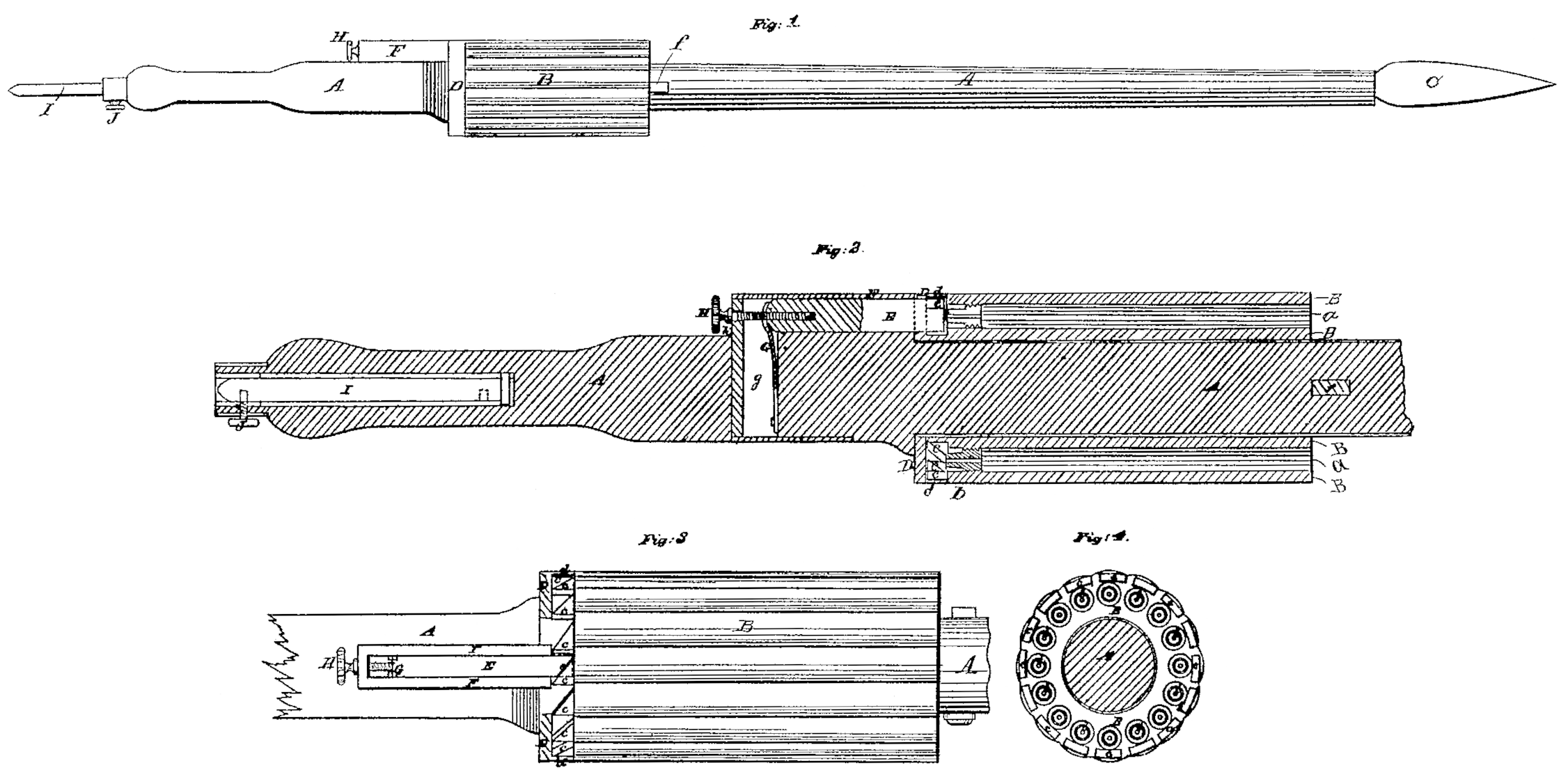
Figure 1 is a side view of my new weapon. Fig. 2 is a central longitudinal section of the revolving cylinder and the back part of the pole or shaft of the lance. Fig. 3 is a top view of the cylinder and part of the pole or shaft, with the recoil-shield and the hammer-casing in section. Fig. 4 is a back view of the cylinder.
Similar letters of reference indicate corresponding parts in the several figures.
This invention consists, first, in the combination, with a lance, of a revolving many chambered cylinder of similar character to that commonly used in revolving fire-arms, arranged to rotate upon the pole or shaft of the lance by having the said pole or shaft passed directly through it.
It also consists in furnishing the so-applied many-chambered cylinder at its rear end with a circular series of ratchet-like teeth corresponding in number with its chambers, and in fitting the lance pole or stock with a sliding hammer, so formed and arranged that by turning the cylinder upon the said pole or shaft the said teeth may be made to force back the said hammer in such manner as to permit it to be driven forward again by a suitably-applied spring, and thereby caused to strike upon percussion-caps or their equivalents, applied in rear of the several chambers for the purpose of firing the charges of the said chambers one at a time and in regular succession all round the cylinder.
It also consists in fitting the butt of the pole or shaft with a spike which can be sheathed by being pushed into the pole or shaft when the weapon is to be carried or used, and protruded from the butt to enable it to be driven into the ground to hold the Weapon in an upright position, ready to be quickly laid hold of when required for use.
This weapon is suitable for arming either infantry or cavalry, but especially for infantry.
To enable others skilled in tie art to make and use my invention, I will proceed to describe its construction and operation.
A is the pole or shaft, which may be either made of wood and have the part to which the cylinder B is fitted and the part in front of the cylinder cased with a steel tube, or made entirely of an iron or steel tube, with the exception of the rear portion, which constitutes the handle, which should be of wood, and of ally suitable length, say from six to seven feet, and of a suitable thickness for proper strength.
C is the lance-head, made of steel, of any suitable form and length, but preferably of such form as to cut both in being pushed forward and in being drawn from a wound, after having been pushed in up to the pole or shaft.
The cylinder B is bored centrally throughout, of a size to fit and turn easily on the pole or shaft A, and its chambers a a are arranged around the bore, at equal distances apart, in a concentric circle.
b b are nipples for percussion-caps, screwed the cylinder in rear of the several chambers.
c c are the ratchet-teeth formed on the rear end of the cylinder, corresponding in number with the chambers.
D is a circular recoil-shield, of steel or other metal, fast upon the pole or shaft A, in rear of the cylinder, and f is a key inserted transversely through the pole or shaft in front of the cylinder, to keep it in place against the recoil-shield, said shield being made with a rim, d, to incase the ratchet-teeth. Two cylinders are intended to be provided, the other of which may be carried loaded in a cartouch-box, and when all the chambers in the first one have been discharged the key f is taken out and that one is drawn off the pole or shaft over the head of the lance, and the other one is put on in its place and secured by the key.
E is the hammer, consisting of a square steel bolt fitted to slide parallel with the length of the pole or shaft A, in a metal box, F, secured to the pole or shaft A in rear of the recoil-shield. This bolt has formed on its front end an inclined surface, e, for the ratchet-teeth to act upon to force it back from the nipples.
G is the spring for driving forward the hammer, applied to work in a transverse slot, g, provided in the pole, and entering the box F in rear of the hammer.
H is a screw, passing freely through a hole, h, in the rear of the box, and screwing into a tapped hole in the rear end of the hammer for the purpose of drawing back the hammer clear of the ratchet-teeth previously to taking out the discharged cylinder, and to prevent the accidental discharge of the chambers of the capped and loaded cylinder.
. I is the spike, inserted into a hole bored for its reception in the butt of the pole or shaft deep enough to receive its whole length, as shown in Fig. 2; and J is a set-screw, transversely screwing into the pole or shaft, to secure the spike either while sheathed, as shown in Fig. 2, or while drawn partly out of the pole or shaft, as shown in red outline in Fig. 1.
This weapon may be carried, in charging on an enemy, with the cylinder grasped in the left and the back part of the pole or shaft in the right hand, and the cylinder being turned by – the left hand brings the chambers successively in front of the hammer, and causes the ratchet-teeth to force back the hammer as each chamber approaches it, and as the teeth severally pass the hammer the latter is driven forward by the spring against the nipples and caused to fire the charges of the chambers. In this way a rapidly-repeated fire is effected until arriving at close quarters, when the lance itself is used.
To change the discharged cylinder for the charged one, which has been kept in reserve, the hammer is drawn back by screwing in the screw H, the key f is taken out, the discharged cylinder is drawn off, the charged one put in its place, the key reinserted, and the screw screwed back far enough to allow the hammer to reach the percussion-caps on the nipples.
To stack arms in bivouacking or encamping, the spike I is drawn out and secured, and by driving down the pole or shaft vertically the said spike is driven into the ground.
What I claim as my invention, and desire to secure by Letters Patent, is—
1. The combination, with a lance, of a many chambered cylinder of similar character to that of a revolving fire-arm, fitted to rotate upon the pole or shaft of the lance, substantially as herein described.
2. The combination of the series of ratchet like teeth on the rear of the so-applied many chambered cylinder, the sliding hammer, and the spring, substantially as and for the purpose herein specified.
3. The movable spike fitted and secured in the butt of the lance pole or shaft, substantially as and for the purpose herein specified.
JAMES C. CAMPBELL.
Witnesses:
M. S. Partridge,
Daniel Robertson.