
British 1722
LETTERS PATENT to James Kerr, of Bedford Terrace, Trinity Square, Southwark, in the County of Surrey, for the Invention of “ Improvements in Revolver Fire-arms.”
Sealed the 25th September 1855, and dated the 28th July 1855.
PROVISIONAL SPECIFICATION left by the said James Kerr at tlie Office of the Commissioners of Patents, with his Petition, on the 28th July 1855.
I, James Kerr, of Bedford Terrace, Trinity Square, Southwark, in the County of Surrey, do hereby declare the nature of the Invention for “ Improvements in Revolver Fire-arms ” to be as follows:—
This Invention has for its object improvements in revolver fire-arms, in order to facilitate the ramming in the balls when loading the short barrels, and for holding or retaining the moveable axis of the short revolving barrels. For this purpose a lever is attached by an axis at one side of the fire-arm, and a sliding ram is used, which slides in a groove or guide at the side of the fire-arnu The lever works in a slot or passage through or in the sliding ram in such manner, that on moving the end of the lever from the side of the firearm, it acts by a curved excentric surface formed on the lever, so as to cause the sliding jam to move into and out of a barrel in a right line, and there is a notch or catch formed in the lever, which holds the axis of the revolving barrels from coming out; and, further, for retaining or holding the axis of the short revolving barrels, a spring catch is applied and a notch is formed in the head or outer end of the axis, so that when the axis is forced into its place the projecting catch or barb of the spring catch reacts, and enters beyond and holds the axis from moving till the spring catch is moved out of the way.
SPECIFICATION in pursuance of the conditions of the Letters Patent, filed by the said Janies Kerr in the Great Seal Patent Office on the 28th January 1856.
TO ALL TO WHOM THESE PRESENTS SHALL COME, I, James Kerr, of Bedford Terrace, Trinity Square, Southwark, in the County of Surrey, send greeting.
WHEREAS Her most Excellent Majesty Queen Victoria, by Her Letters Patent, bearing date the Twenty-eighth day of July, in the year of our Lord One thousand eight hundred and fifty-five, in the nineteenth year of Her reign, did, for Herself, Her heirs and successors, give and grant unto me, the said James Kerr, Her special licence that I, the said James Kerr, my executors, administrators, and assigns, or such others as I, the said James Kerr, my executors, administrators, and assigns, should at any time agree with, and no others, from time to time and at all times thereafter during the term therein expressed, should and lawfully might make, use, exercise, and vend, within the United Kingdom of Great Britain and Ireland, the Channel Islands, and Isle of Man, an Invention for “ Improvements in Revolver Fire-arms,” upon the condition (amongst others) that I, the said James Kerr, my executors or administrators, by an instrument in writing under my, or their, or one of their hands and seals, should particularly describe and ascertain the nature of the said Invention, and in what manner the same was to be performed, and cause the same to be filed in the Great Seal Patent Office within six calendar months next and immediately after the date of the said Letters Patent.
NOW KNOW YE, that I, the said James Kerr, do hereby declare the. nature of the said Invention, and in what manner the same is to be performed, to be particularly described and ascertained in and by the following statement thereof, that is to say:—
This Invention has for its object improvements in revolver fire-arms, in order to facilitate the ramming in the balls when loading the short barrels, and for bolding or retaining tbe moveable axis of tbe short revolving barrels. For this purpose a lever is attached by an axis at one side of the fire-arm, and a sliding ram is used, which slides in a groove or guide at the side of the firearm. The lever works in a slot or passage through or in the sliding ram in such manner, that on moving the end of the lever from the side of the firearm, it acts by a curved excentric surface formed on the lever, so as to cause the sliding ram to move into and out of a barrel in a right line, and there is a notch or catch formed in the lever, which holds the axis of the revolving barrels from coming out; and, further, for retaining or holding the axis of the short revolving barrels, a spring catch is applied and a notch is formed in the head or outer end of the axis, so that when the axis is forced into its place the projecting catch or barb of the spring catch reacts, and enters beyond and holds the axis from moving till the spring catch is moved out of the way.
And in order that my said Invention may be most fully understood and readily carried into effect, I will proceed to describe the Drawing annexed.
Description of the Drawing.
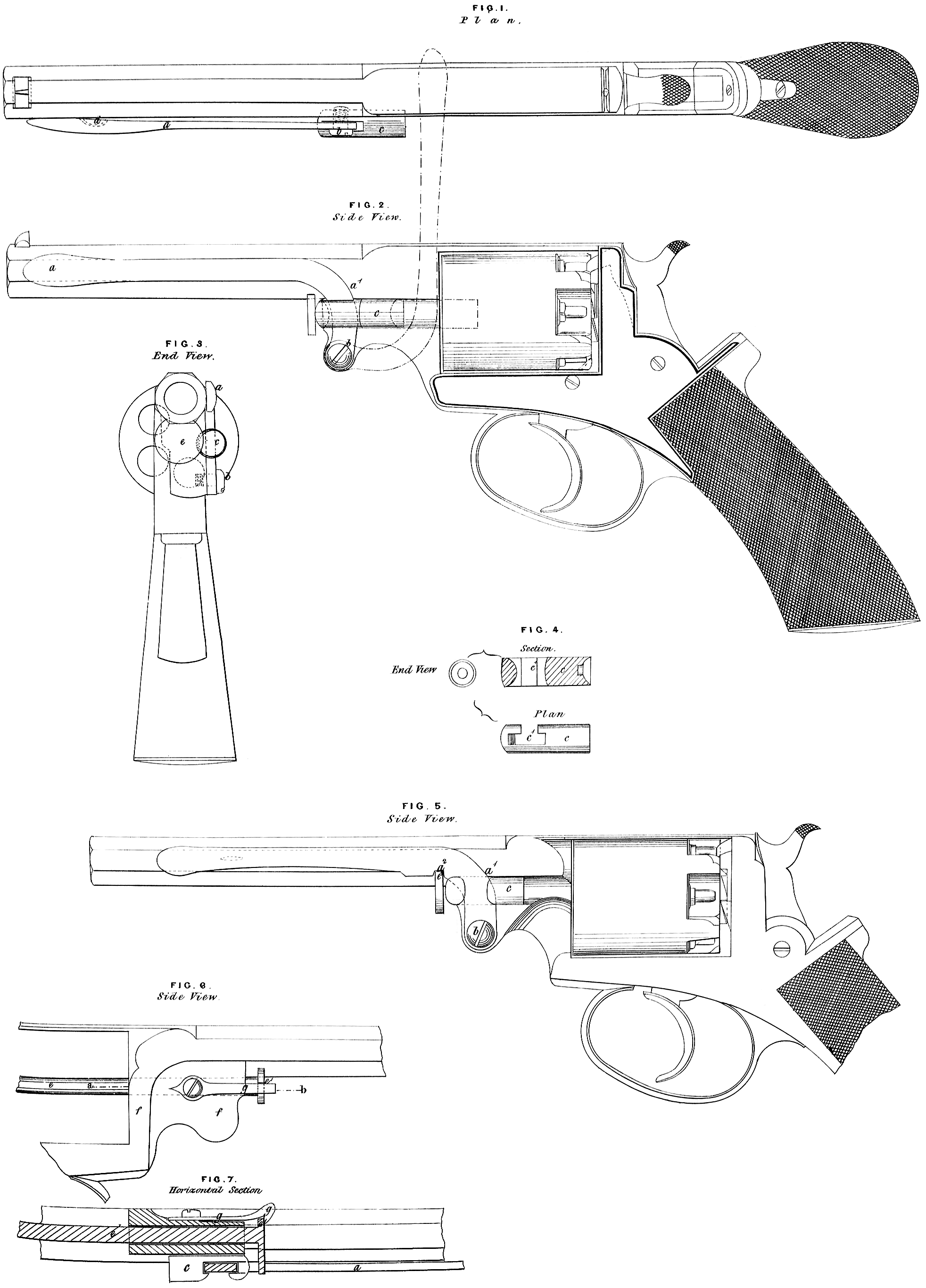
Figure 1 is a plan, Figure 2 a side view, and Figure 3 an end view, of a revolver pistol with the improved ramming apparatus attached, a is a lever, which is attached at one end to the frame of the pistol by the screw b, on which it turns as on a centre; a1 is a curved excentric surface formed on the lever ; c is a sliding ram, shown separately at Figure 4 ; it slides in a groove in the frame of the pistol, as is clearly shown at Figure 3. The sliding ram c has through or in it a slot or passage c\ through which the lever a passes ; thus it will be seen that by raising the lever a into the position shown by red lines in Figure 2, the sliding ram c will be operated upon by the curved excentric suiface a1 of the lever a, and will be forced thereby into one of the short barrels of the pistol so as to ram the charge, d is a projection formed on the side of the barrel, and there is a corresponding indentation in the lever a into which it enters, so as to retain the lever in the position shown in the Drawings until force is applied to spring the lever over the projection d. Figure 5 shows a side view of a pistol, in which the lever a has a notch a2 formed in it, which catches over the head of the centre pin or axis of the short revolving barrels, so as to retain it in its place. In this view the sliding ramc is shown in a slightly modified form. Figure 6 is a side view, and Figure 7 a horizontal section, of part of a pistol, shewing the manner in which I apply a spring catch to retain the centre pin or axis of the short revolving barrels. e is the centre pin or axis, in the head of which is formed a notch e1; / is part of the frame of the pistol, to which the spring catch g is attached. Thus i will be seen that when the centre pin or axis e is pushed in, it will be caugh by the catch g, and cannot be removed without raising the catch.
I would remark, that although I have, to illustrate my Invention, shown m: improvements applied to a pistol, I do not confine myself to so applying them as they are also applicable to other description of revolving fire-arms.
In witness whereof, I, the said James Kerr, have hereunto set my hanc and seal, this Twenty-sixth day of January, in the year of our Lore One thousand eight hundred and fifty-six.
JAMES KERR. (l.s.)
Witness, j
Geo. Pitt,
4, Old Square.