
Britain 2258
A.D. 1872, 29th July. № 2258.
Breech-loading Revolver Fire-arms.
LETTERS PATENT to John Adams, of the Strand, in the County of Middlesex, Revolver Manufacturer, for the Invention of “Improvements in the Construction of Breech-loading Revolver Fire-arms.”
Scaled the 28th January 1878, and dated the 29th July 1872.
PROVISIONAL SPECIFICATION left by the said John Adams at the OKce of the Commissioners of Patents, with his Petition, on the 29th July 1872.
I, John Adams, of the Strand, in the County of Middlesex, Revolver Manufacturer, do hereby declare the nature of the said Invention for “Improvements in the Construction of Breech-loading Revolver Fire-arms,” to be as follows:—
This Invention consists in the, construction of breech-loading revolver fire-arms in such a manner that the ejector or rod for removing the empty cartridge cases from the revolving chambers will, when not in use, partially lie in the centre of the cylinder rod, and is thus protected from the chances of being accidentally bent, and also tends to make the arm more convenient in use. This is effected by attaching a carrier to the front of the frame of the revolver fire-arm by means of a screw or pivot.
This carrier contains a tubular guide through which the ejector works, and it is so arranged that the tubular guide coincides with the hole in the centre of the cylinder rod in one position, and with the chambers of the revolving cylinder in another position. The ejector is secured to the carrier by means of a fixed head at one and and a moveable head at the other, and is kept in position by means of a spring.contained in the interior of the tubular guide.
When the ejector is required to be used for ejecting the empty cartridge eases from the chambers of the revolving cylinder, the carrier is turned outwards until the tubular guide containing the ejector is opposite the chamber; the ejector is then forced into the chamber and the empty cartridge case ejected. For the purpose of preventing it from being turned beyond the necessary point, the carrier has within itself a moveable bolt which is inserted in an aperture provided for its reception, and which bolt is actuated and kept in position by means of a spiral spring, the whole being secured by a screw inserted into the outer end of the aperture, and this screw is prevented from becoming loose by means of the head of the screw or pivot on which the carrier turns being made suKciently large to partially cover it. A slot is formed of the requisite size and depth in front of the frame of the revolver fire-arm for the end of the spring bolt contained within the carrier to work in. The length of this slot regulates the distance the carrier should traverse. At each end of this slot a conical recess is formed so as to keep the carrier in position both when the tubular guide is opposite the chamber of the cylinder and the centre hole in the cylinder rod, which is made hollow for the reception of the ejector.
The cylinder is locked in position when the ejector is being used for ejecting the cartridge cases by means of a bolt carrying within itself a, spiral spring, both of which are kept in position by a screw which is inserted into the opposite side of the frame and closing the hole through which the bolt and spring pass. This bolt works through the face of the frame and fits into two recesses or notches formed respectively at either end of the cylinder rod, so as to secure it when in its normal position or when withdrawn for the purpose of removing the revolving cylinder. A circular groove of the size and circumference of the cylinder rod is cut into this bolt, and when it is required to withdraw the cylinder rod or push it into its normal position this bolt is depressed by the thumb until the cylinder rod can be withdrawn or pushed in, as may be required. On removing the pressure the bolt is fixed by the spiral spring into one of the two recesses or notches cut in either end of the cylinder rod.
SPECIFICATION in pursuance of the conditions of the Letters Patent, filed by the said John Adams in the Great Seal Patent Office on the 29th January 1873.
TO ALL TO WHOM THESE PRESENTS SHALL COME, I, John Adams, of the Strand, in the County of Middlesex, Revolver Manufacturer, send greeting.
WHEREAS Her most Excellent Majesty Queen Victoria, by Her Letters Patent, bearing date the Twenty-ninth day of July, in the year of our Lord One thousand eight hundred and seventy-two, in the thirty-sixth year of Her reign, did, for Herself, Her heirs and successors, give and grant unto mc, the said John Adams, Her special licence that I, the said John Adams, my executors, administrators, and assigns, or such others as I, the said John Adams, my executors, administrators, and assigns, should at any time agree with, and no others, from time to time and at all times thereafter during the term therein expressed, should and lawfully might make, use, exercise, and vend, within the United Kingdom of Great Britain and Ireland, the Channel Islands, and Isle of Man, an Invention for “Improvements in the Construction of Breech-loading Revolver Fire-arms” upon the condition (amongst others) that I; the said John Adams, my executors or administrators, by an instrument in writing under my, or their, or one of their hands and seals, should particularly describe and ascertain the nature of the said Invention, and in what manner the same was to be performed, and cause the same to be filed in the Great Seal Patent Office within six calendar months next and immediately after the date of the said Letters Patent.
NOW KNOW YE, that I, the said John Adams, do hereby declare the nature of my said Invention, and in what manner the same is to be performed, to be particularly described and ascertained in and by the following statement, reference being had to the Drawings hereunto annexed and to the figures and letters marked thereon, that is to say:—
My said Invention consists in the construction of breech-loading revolver fire-arms in such a manner that the ejector or rod for removing the empty cartridge cases from the revolving chambers will when not in use partially be in the centre of the cylinder rod, and is thus protected from the chance of being accidently bent, and also tends to make the arm more convenient in use. This is effected by attaching a carrier to the front of the frame of the revolver fire-arm by means of a screw or pivot. This carrier contains a tubular guide through which the ejector works, and is so arranged that the tubular guide coincides with the hole in the centre of the cylinder when in one position, and with the chambers of the revolving cylinder when in another position. The ejector is secured to the tubular guide by means of a fixed head at one end and a moveable head at the other end, and is kept in position by means of a spring contained in the interior of the tubular guide.
When the ejector is required to be used for ejecting the empty cartridge cases from the chambers of the revolving cylinder the carrier is turned outwards until the tubular guide containing the ejector is opposite the chamber, the ejector is then forced into the chamber and the empty cartridge case ejected. Por the purpose of preventing it from being turned beyond the necessary point the carrier has within itself a moveable bolt, which is inserted in an aperture provided for its reception, and which bolt is actuated and kept in position by means of a spiral spring, the whole being secured by a screw inserted into the outer end of the aperture, and this screw is prevented from becoming loose by means of the head of the screw or pivot on which the carrier turns, which is made sufficiently large to partially cover it. A slot is formed of the requisite size and depth in front of the frame of the revolver fire-arm for the end of the spring bolt contained within the carrier to work in. The length of this slot regulates the distance the carrier should traverse. A.t each end of this slot a conical recess is formed so as to keep the carrier in position, both when the tubular guide is opposite the chamber of the cylinder and when opposite the centre hole in the cylinder rod, which is made hollow for the reception of the ejector.
The cylinder rod is locked in position when the ejector is being used for ejecting the cartridge cases by means of a bolt carrying within itself a spiral spring, both of which are kept in position by a screw which is inserted into the opposite side of the frame, and closing the hole. through which the holt and spring pass. This last mentioned bolt works through the face of the frame and fits into two recesses or notches, formed respectively at either end of the cylinder rod so as to secure it when in its normal position or when withdrawn for the purpose of removing the revolving cylinder. A circular groove of the size and circumference of the cylinder rod is cut into this bolt, and when it is required to withdraw the cylinder rod or push it into its normal position the bolt is depressed by the thumb until the cylinder rod can be withdrawn or pushed in as may be required. On removing the pressure the bolt is forced by the spiral spring into one. of the two recesses or notches cut in either end of the cylinder rod.
I will now proceed to refer to the accompanying Drawings from which the nature of my said Invention will be more clearly understood.
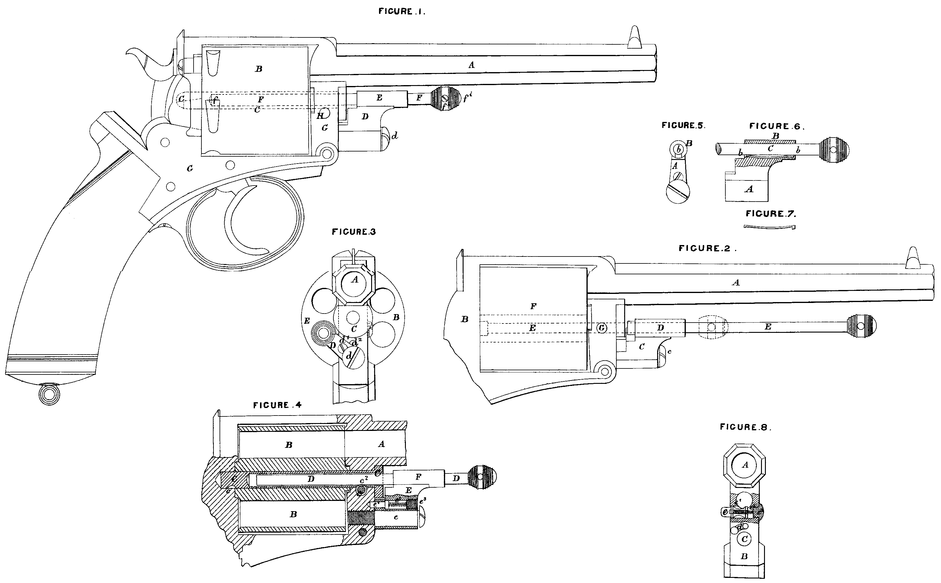
Figure 1 is a side view of a revolver fire-arm, shewing the ejector in the centre of the cylinder rod. A is the barrel of the revolver fire-arm; B, the revolving cylinder; C, the hollow cylinder rod, which is shewn in dotted lines; D, the carrier, carrying the’ tubular guide E through which the ejector F works, d being the screw or pivot with the large head on which the carrier turns; E is the tubular guide; P, the ejector, working through the same, f being the fixed head at one end of the ejector F, and, f¹ the moveable head secured by means of the small screw f² to the other end; G is the frame of the revolver; and H is the small bolt which keeps the cylinder rod in position.
Figure 2 is a side view of a, barrel and portion of the frame of a revolver with the revolving cylinder removed. A is the barrel; B, the frame; C, the carrier; e, the screw or pivot on which the same turns; D, the tubular guide; E, the ejector; F, the cylinder rod, with the ejector lying in its centre, shewn, in,dotted lines; G, the small bolt, which keeps the cylinder rod in position.
Figure 3 is a front view of a portion of a revolver, shewing the ejector in position, for ejecting the empty cartridge cases; A is the. barrel; B, the revolving cylinder; C, the hollow cylinder roil; D, the carrier, d being the head of the screw or pivot on which the same turns; d¹, the screw which keeps the spring bolt contained in the carrier in position; and d², the slot cut in the front of the frame for the spring bolt to work in; and E is the ejector.
Figure 4 is a longitudinal section of the revolving cylinder, and portion of the frame and barrel of a revolver constructed in accordance with my present Invention. A. is the barrel; B, the revolving cylinder; C, the hollow cylinder rod with the ejector D, the latter being partially in its centre; c, the small bolt, which keeps the cylinder rod in position; c¹ dud c² are two recesses or notches cut in either end of the cylinder rod for its reception; E is the carrier; e, the screw or pivot on which it turns; e¹, the small bolt contained in the carrier, and actuated by the small spiral spring c², which is kept in position by the screw c³, and F is the tubular guide.
Figures 5 and 6 are views of the carrier and tubular guide, shewing he position of the spring contained therein for the purpose of keeping the ejector in its position. A. is the carrier; B, the tubular guide; b the spring; and C, the ejector; and Figure 7 is a detached view of the spring b.
Figure 8 is a portion of’ the front of a frame of a revolver, shewn partly in section. A is the barrel; B, the frame; C, the hole into which the screw or pivot on which the carrier turns enters, d being the slot with the conical recess at each end, in which the small bolt contained in the carrier works; e is the small spring bolt winch holds the cylinder rod in position, e’ being the circular groove of the size and circumference of the cylinder rod cut therein; e², the small spiral spring which keeps the bolt in position; and e³, the screw which secures the whole.
Having thus described and ascertained the nature of my said Invention, and in what manner the same is to be performed, I would observe in conclusion that what I consider novel and original and therefore claim as constituting the Invention secured to me by the said herein-before in part recited Letters Patent is, the combination and arrangement of parts and mechanism in the construction of breech-loading revolver fire arms, in the manner and for the purposes herein-before set forth and described, or any mere modifications thereof.
In witness whereof, I, the said John Adams, have hereunto set my hand and seal, this. Twenty-eighth day of January, in the year of our. Lord One thousand eighth hundred and seventy-three.
JOHN ADAMS. (L.S)