
US 72844
UNITED STATES PATENT OFFICE.
JOHN GORDON, OF NEW LONDON, CONNECTICUT.
IMPROVEMENT IN SPRING-POWER REPEATING FIRE-ARMS.
Specification forming part of Letters Patent No. 72,844, dated December 31, 1867.
To all whom it may concern:
Be it known that I, JOHN GORDON, of the city and county of New London, of the State of Connecticut, have invented a new and useful Improvement in Fire-Arms; and do hereby declare the same to be fully described in the following specification and represented in the accompanying drawings, of which–
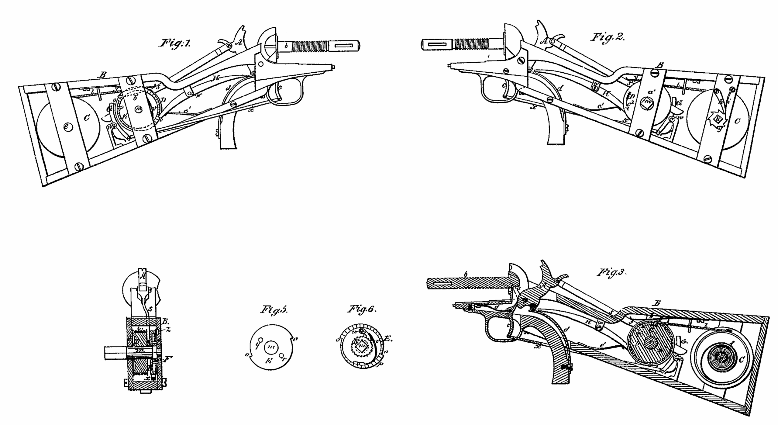
Figures 1 and 2 are side views of my invention as applied to the breech of a revolver fire-arm. Fig. 3 is a longitudinal section of the same. Fig. 4 is a transverse section taken through the shaft of the winding-barrel and mechanism connected therewith.
The object of my invention is to raise the hammer to cock by a mechanical power separate from the trigger.
I am aware that in revolvers the hammer has been raised to cock by manual power applied through the trigger. In my invention, however, the trigger in no respect operates to effect the elevation of the hammer by manual power exerted on the trigger, but is employed in the usual way to effect the discharge or depression of the hammer by means of its spring.
In the case of application of my invention to a revolver its hammer may be supposed to have a pawl or mechanism applied to it for effecting by means of a ratchet the intermittent revolution of the rotary magazine or cylinder, such pawl or mechanism being exhibited in dotted lines at a in Fig. 3.
In the drawings, A denotes the cock or hammer, and B the stock of a revolver-gan, the spindle of the cylinder or magazine being shown at b. The trigger is seen at c. The mainspring for throwing the hammer down is exhibited at d.
Within the stock B, I arrange a pulley or wheel, C, to revolve on an arbor, e. A spiral spring, f, contained within the wheel C and encompassing the arbor, has one end affixed to the arbor and the other to the rim of the pulley. Furthermore, there is on the arbor a ratchet, g, which operates with a click, h, pressed up to the periphery of the ratchet by a spring, i, the same being as shown in Fig. 2. By applying a key to the pyramidal head or part k of the arbor and turning the arbor the spring may be wound up to such a degree of tension as may be desirable.
To the periphery of the wheel C a cord, l, is attached at one of its ends, such cord being carried around such periphery several times and attached at its other end to the circumference of another wheel, D, fixed upon another or winding-arbor, m, such arbor being arranged in the stock in manner as represented. There revolves on such arbor an escapement-ratchet, E, formed as shown in side views in Figs. 5 and 6–that is to say, it has two shoulders, o o, on its circumference, and a range, p, of teeth formed on its outer side and close to its circumference. From its inner side two studs or pins, q r, project toward the wheel D. They are to operate with a hooked pawl or arm, s, which is arranged between the wheel D and the ratchet E, is jointed to the hammer or cock A, and is formed as represented.
Aside of the rotary escapement-ratchet E is another or auxiliary ratchet, F, which is fixed on the arbor m, so as to revolve with it. A click, t, supported on a stud, u, projecting from the ratchet E, engages with the ratchet F, and is pressed up to the periphery by a spring, v, fixed to the side of the ratchet E.
Two lever-pawls, G H, supported on fulcra w w, are arranged with respect to the ratchet E and the mainspring d, in manner as exhibited in Fig. 1. The first of these pawls–viz., that marked G–has its lower arm connected to the lower end of the trigger by a rod, x, which is jointed both to the pawl and the trigger. The other lever-pawl, H, has its rear arm resting against a spring, c’, by whose action the pawl will be pressed against the escapement-ratchet.
A spring, y, fixed to the stock and resting on the hooked pawl s, serves to press such pawl downward. A spring-click, z, fixed to the inner face of one of the arbor-supporters a’ b’, operates with the range p of teeth of the escapement-ratchet E, and serves to prevent back motion of such ratchet while the arbor m is in the act of being revolved so as to wind up the cord l on the wheel D for the purpose of contracting the spring within the wheel C. If, now, we suppose a key to be applied to the arbor m, and such arbor to be thereby revolved in the direction of the arrow c2, so as to wind up the cord on the wheel D and unwind it from the wheel C, the escapement-ratchet E will be stationary during the said winding process; but the moment the arbor is relieved from power exerted to revolve it it will rotate the escapement-wheel so as to carry one of its studs q’ r against the shoulder of the hook of the pawls and draw such pawl back, so as to cause it to raise the hammer A to full-cock. On the hammer being so raised the escapement-ratchet will bring up against and be estopped by the lever-pawl H. On the trigger being pulled backward the spring d by its superior elastic force will act against the longer arm of the lever-pawl H and throw the pawl out of engagement with the escapement-ratchet, the hammer will be thrown down upon the nipple, and the other lever-pawl, G, will be thrown into engagement with the escapement-ratchet, so as to catch and hold it after its partial revolution forward, occasioned by the draft of the hooked pawls upon it. The so catching the escapement-ratchet by the pawl G will cause the wheel to be stopped. On allowing the trigger to be advanced by its usual restoring-spring (shown at o’) the pawl G will be thrown out of engagement with the escapement-wheel, which will instantly be revolved by the power of the spring in the wheel C, and the hammer will be drawn back to cock, the escapement-wheel bringing up against and being estopped by the pawl-lever H.
From the above it will be seen that the automatic mechanism for cocking the hammer will perform this function instantly after the hammer may have been thrown down by its spring, and thus the holder or user of the repeating fire-arm or revolver will not be obliged to cock the hammer by his hand preparatory to each discharge of it. Thus his whole attention may be directed to aiming and firing his piece. The cocking of the hammer will also cause the charge-cylinder to be revolved so as to bring a fresh charge up to the barrel.
I do not claim the combination of the trigger and hammer of a fire-arm with a mechanism by which, by manual power exerted through the trigger, the hammer may be raised or cocked preparatory to being discharged. Nor do I claim as my invention the combination of the trigger, the hammer, and a mechanism as described, (or its equivalent,) which, by the power of a spring or its mechanical equivalent, shall effect the elevation of the hammer after each pull on the trigger, as specified, the hammer being depressed by its mainspring, as set forth.
What I do claim as my invention is–
The combination as well as the arrangement of parts for effecting the retraction of the hammer after a pull on the trigger, such consisting of the spring f and its wheel C, the cord l and winding-wheel D, or the equivalent thereof, the hooked pawl s, the escapement-wheel E and its click t and ratchet F, and the lever pawls G H, applied to the trigger A and the mainspring d, as set forth.
JOHN GORDON.
Witnesses:
R. H. EDDY,
F. P. HALE, Jr.