
US 184145
UNITED STATES PATENT OFFICE.
IDA. COCHRAN, OF NEW HAMBURG, NEW YORK, ADMINISTRATRIX OF JOHN W. COCHRAN, DECEASED.
IMPROVEMENT IN REVOLVING FIRE-ARMS.
Specification forming part of Letters Patent No. 184,145, dated November 7, 1876; application filed May 8, 1874.
To all whom it may concern:
Be it known that John W. Cochran, late of the city, county, and State of New York, now deceased did in his lifetime make an invention of certain new and useful Improvements in Revolving Fire-Arms, and that the following is a full, clear, and exact description and specification of the same.
The said invention has reference to revolving fire-arms, having a revolving cylinder suitable for being loaded with metallic cartridges; and its object is to enable two or more of the cartridges, or the remnants thereof after firing to be withdrawn from the chambers simultaneously.
To this end the invention consists of certain combinations of the said revolving cylinder with two or more extractors and with other devices, which are set forth it detail at the close of this specification.
In order that the invention may be fully understood, a revolving fire-arm embodying the same in one of the forms devised by the said Cochran, is represented in the accompanying drawings.
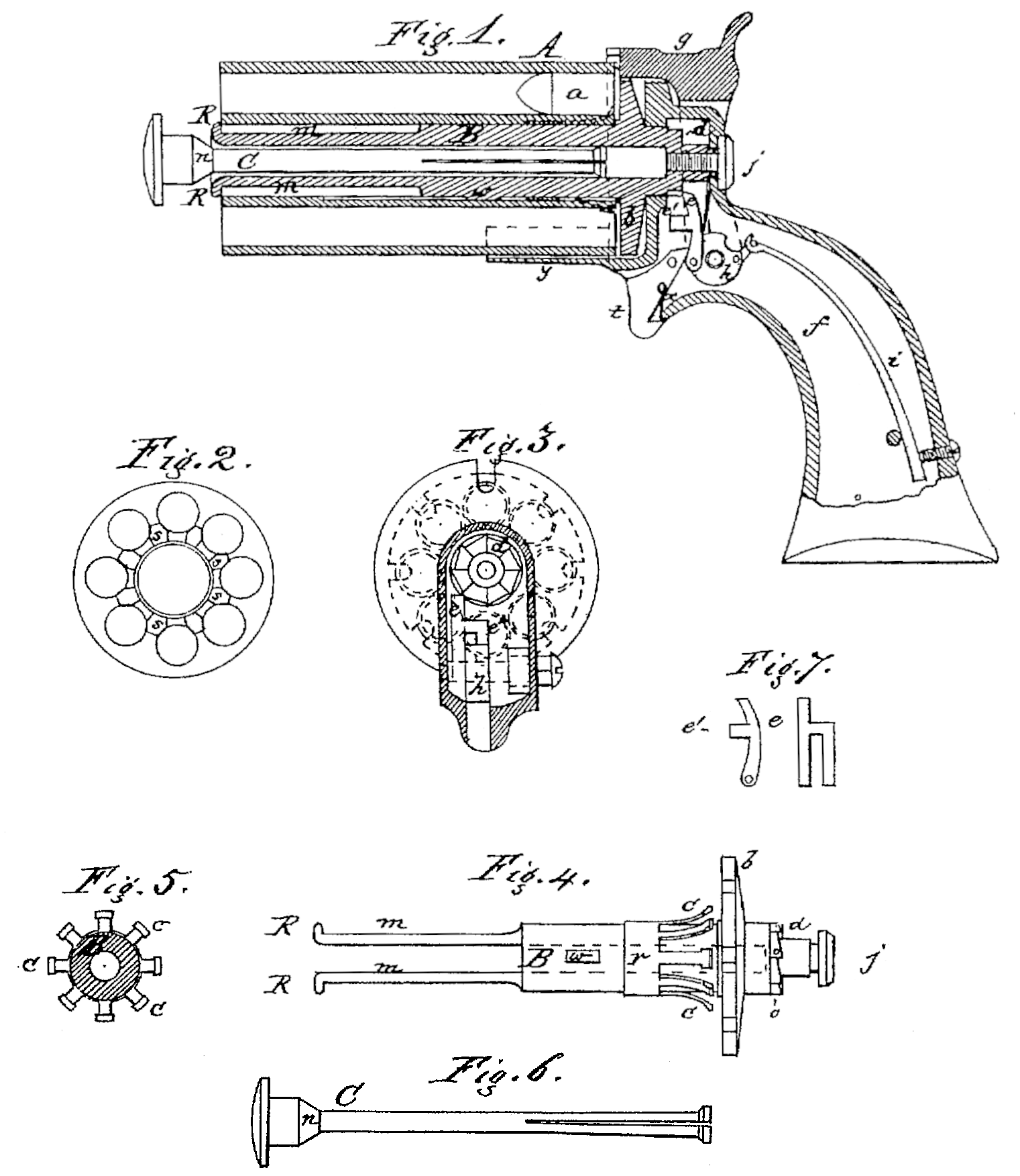
In said drawings, Figure l represents a central longitudinal section of the revolving fire-arm, with the lock-rod slightly drawn. Fig. 2 represents a view of the rear of the revolving cylinder. Fig. 3 represents a transverse section of the fire-arm, showing the recoil-plate and the ratchet-teeth for revolving the cylinder. Fig. 4 represents a view of the shaft of the revolving cylinder. Fig. 5 represents an end view of the extractors for removing the remains of the cartridges after firing them, or to unload the chambers when they are not to be used. Fig.6 represents the lock-rod for securing the cylinder. Fig. 7 represents two views of the pawl for turning and holding the cylinder in proper position for being fired.
In the said drawings, A represents the cylinder, having its chambers bored through at the rear for the reception of the metallic cartridges a a containing the powder and ball, as well as the percussion-powder for firing it. The cylinder is fitted upon a central shaft, B, which extends through it, and extends also into the look-frame, in which it is constructed to turn. The shaft is made fast to the lock-frame by the screw j, and is provided with ratchet-teeth d, which are turned by a pawl, e, worked by the cock g, the pawl being pivoted at its lower end to the tumbler h of the shaft to which the cock is secured. The pawl has a projection, e’, on one of its sides, which engages into ratchet-teeth o o on the outside of the shaft B, inclined in the opposite direction to those (d) which engage with the pawl o, so that when the pawl is raised the projection e’ comes into the proper position to be struck by one of the outside ratchet teeth, aid to hold the shaft oppositely from the pawl.
The cylinder A. is compelled to turn with the shaft B by the action of a spline, w, which engages in a groove formed in the wall of the cylinder. This groove extends from the rear of the cylinder forward, so as to permit the shaft with its spline to be drawn out of the cylinder. The recoil-plate b is fast to the shaft B. The shaft B extends through the front end of the revolving cylinder. It is bored centrally and is slotted longitudinally for a portion of its length, which also is reduced in diameter, so as to form two spring-times, m m, with hook so as to form two spring-times, man, with hook-formed leads R, which can be forced outward so as to lap over and hold the front end of the cylinder. These heads are forced outward so as to secure the cylinder by means of the lock-rod C, which is inserted into the bore of the shaft, aid has a head with a conical shoulder, n, so that when the lock-rod is pushed into the bore of the shaft its shoulder compels the heads R, of the tines of the shaft to separate and lap over the front end of the cylinder. The lock-rod, when so inserted, is old in place by friction, its inner end being split so that its sides form springs, which spring apart and bear against the wall of the bore of the shaft.
In order to remove the cartridges or the remnants thereof that remain after firing from all the chambers simultaneously, as many extractors c c are provided as there are chambers.
In the form of revolver represented in the drawings each extractor is a spring, and projects from a ring-stock, r, that connects the extractors with the shaft B, so that the said shaft forms a stern for the extractors.
The central hole in the cylinder is counterbored from the rear forward, to permit the ring-stock r to enter it, and the shoulder at the front end of the counterbored portion abuts against the ring-stock and holds the rear end of the cylinder sufficiently in advance of the face of the recoil-plate to permit the flanges of the cartridges to intervene between the two. The rear end of the cylinder is slotted around the central stem, as seen at s s Fig. 2, so that, when the cylinder is charged with cartridges and is moved endwise upon the shaft or stem, or the shaft or stem is shoved endwise into the cylinder, the heads of the extractors can spring over the flanges or heads of the cartridges and take their places in advance of those flanges. The frame f of the pistol holds the mainspring i, the cock h, and the pawl e, for operating the ratchet. It also holds the trigger t and sear-spring w, and it has a guard, y, to prevent the forefinger from touching the cylinder when it is being turned.
In putting the pistol in working order the shaft or stem B is secured in the lock-frame by the screw i, so that it can be revolved by the pawl. The extractors c c are secured to the shaft by screws passing through their ring-stock, or in any other convenient way. The cylinder is then pushed onto the shaft B. The lock-rod C is passed into the hole in the shaft, and when its head is forced in the times of the shaft will be forced outward, so that the heads of the tines will firmly hold the cylinder in its place on the shaft in advance of the recoil shield.
When the lock-rod is withdrawn a part of the way the cylinder may be drawn forward on the shaft or stem, or the shaft or stem may be pulled rearward through the cylinder to cause the extractors to act on all the dead or used up cartridge-shells, so as to permit the user to insert others, and to return the cylinder to its place against the recoil-shield, and lock it by pushing back the lock-rod.
In this example there is an extractor for each shell arranged to pass in between the shells or charges nearly one-third of their diameter, so that there is a corner of an extractor pushing on each side of each shell against the flange or head, which is sure to clear the chambers without trouble or loss of time. The extracting should be done immediately after firing while the grease upon the shells is warm.
The cylinder can be readily removed from the shaft upon withdrawing the locking-rod, and the shaft may be removed from the lock frame upon the removal of the screw j. An ordinary direct-acting lock is used.
The extractors need not necessarily be attached to the shaft, as the said John Cochran arranged them in other ways. Thus, for example, they may be made in the form of a spring-hook and connected with the recoil plate, the bill of each hook being in such case made to enter into the chamber through a slot in the cylinder and take its place in advance of the head of the cartridge-shell.
The lock-rod may be secured in place by cutting a screw on its periphery to engage with a screw-thread in the bore of the shaft. One or two extractors may be used for each chamber.
I claim as the invention of the said John W. Cochran, deceased—
1. In combination with a rotating cylinder, all extractor fitted upon a center-pin, said extractor having projections with sufficient out ward and inward movement to accomplish the object specified.
2. The split central shaft, having an exterior shoulder upon the outer end, in combination with the pin inserted therein to retain the cylinder in position upon said shaft, substantially as set forth.
3. The central shaft, having its rear end rotate in two bearings to give increased steadiness of motion, in combination with the extractor, and the rotating recoil-plate at the base of said extractor, substantially as set forth.
Witness my hand this 30th day of March, A. D. 1874.
IDA COCHRAN,
Executrix of John W. Cochran.
Witnesses:
Wm. O. Hicks,
Wm. B. Millard.