
US 15797
UNITED STATES PATENT OFFICE.
JOSEPH ADAMS, OF CLEVELAND, OHIO.
IMPROVEMED FIRE-ARMS.
Specification forming part of Letters Patent No. 15,797, dated September 30, 1856.
To all whom it may concern:
Be it known that I, Joseph Adams, of Cleveland, in the county of Cuyahoga and State of Ohio, have invented a new and Improved Revolving-Barrel Fire-Arm; and I do hereby declare that the following is a full and exact description thereof, reference being had to the accompanying drawings, making a part of this specification.
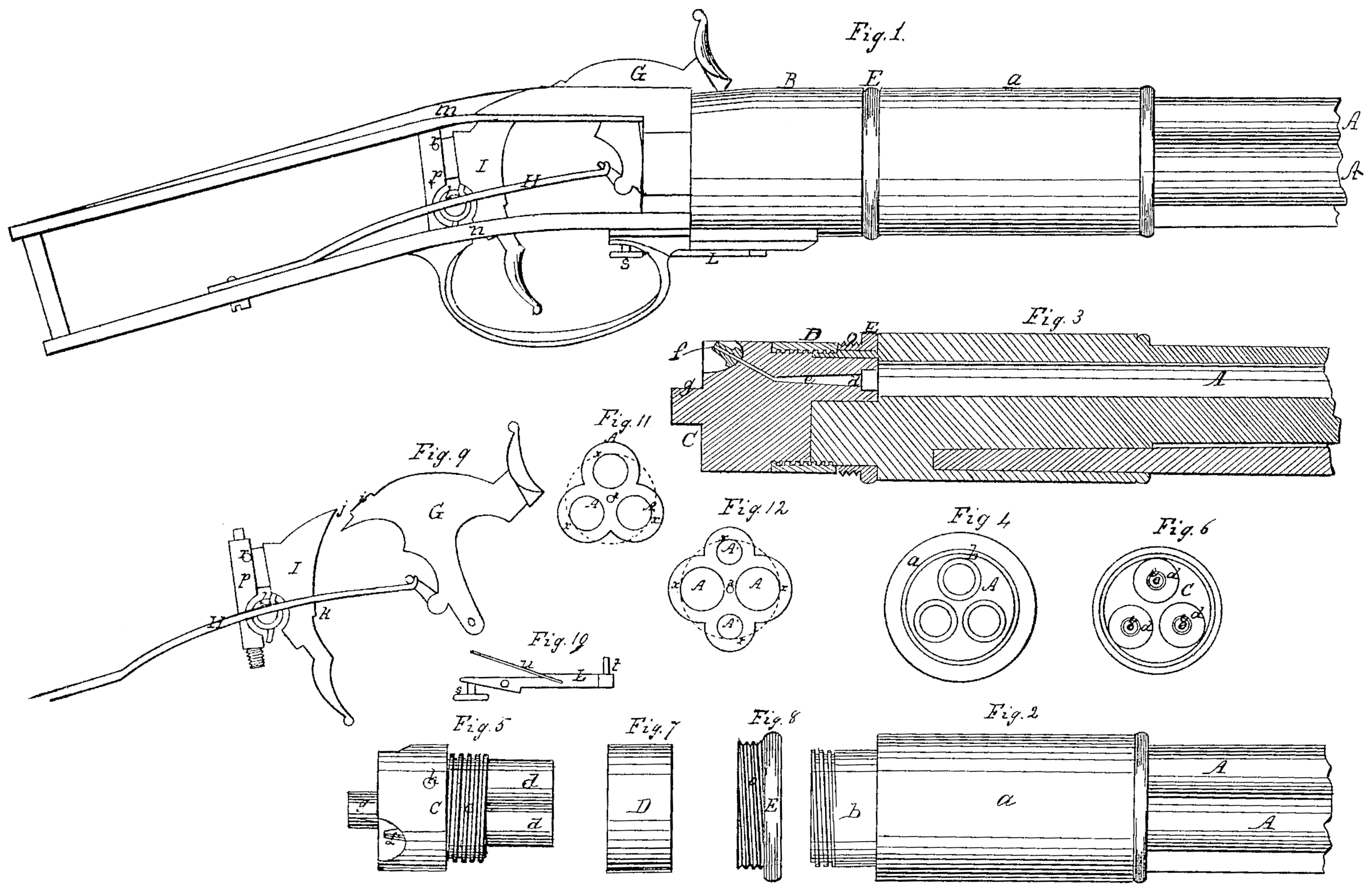
Figure 1 is a side view of a three-bore rifle constructed in my improved manner, the stock being removed to enable the construction of the lock and breech to be seen; Fig. 2, a side view of the breech of the barrel detached; Fig. 3, a vertical central section of the breech of the barrel, together with the removable breech-pin, the nut which secures the same to the barrel, and the collar by which the barrel is secured within the socket; Fig. 4, a view of the rear end of the barrel, the breech-piece being removed; Fig. 5, a side view of the breech-piece; Fig. 6, an end view thereof; Fig. 7, a side view of the nut by which the breech-piece is secured in the breech of the barrel; Fig. 8, a view of the collar by which the barrel is secured in the socket; Fig.9, a side view of the lock detached; Fig.10, a view of the trigger or catch by which the breech is allowed to revolve and is held in the proper positions; Fig. 11, end view of the muzzle of the triple-bore barrel; Fig. 12, end view of the muzzle, showing a modification in which four bores may be arranged in the barrel on the same principle.
Like letters designate corresponding parts in all the figures.
The nature of my invention consists in the arrangement of a single revolving barrel with three or four bores in such a manner as to secure.the utmost economy of space and weight and at the same time to retain the usual strength, while the outer most points of the several bores are rendered concentric with the center around which the barrel turns; secondly, in the employment of a removable compound breech-piece having branches which fit respectively into countersinks at the rear ends of the bores, and in the application of a right-and-left nut fitting corresponding screw-threads, respectively, on the barrel and breech-piece, whereby the breech-piece is drawn and retained in the barrel, said nut serving also to hold the revolving collar by which the barrel secured in the socket, and thus united to the stock; thirdly, in the peculiar arrangement of a hammer, trigger, and mainspring supplying the place of an ordinary gun-lock, to suit the peculiar construction of the gun, substantially as herein set forth.
I construct the barrel either with three or four bores. No greater or less number will fulfill the intended purpose. When three bores are employed, as represented in the drawings, their centers are placed in the angles of an equilateral triangle and the diameters of the bores are all equal, so that the outermost tangents of the several bores shall all coincide with the circumference of a circle whose center is the same as that on which the barrel turns in revolving, as illustrated in Fig.11, where the outermost tangents of the three barrels AAA are shown to be coincident with the dotted circle x, concentric with the center a of the barrel’s revolution.
The modification shown in Fig. 12 shows the arrangement of four bores in the barrel on the same principle and fulfilling the same conditions. In this case two opposite bores, AA, are of large caliber— say of suitable size for shot— while the intermediate opposite bores, A’ A’, are of smaller caliber— say of suitable size for the ordinary rifle-ball. By this arrangement only of two larger and two smaller bores can the outermost tangents thereof. be arranged in the same circle x, concentric with the center a, around which the barrel turns, and at the same time permit the greatest economy in the size and weight of the barrel. Whether three or four barrels are employed the thickness of metal, both outside and between the several bores, is nearly uniform, and the outer surface is consequently fluted, as represented; or the outer periphery of the barrel may be only rounded or slightly corrugated. It will be seen that the bores are in this way brought as close as possible to each other in the center of the barrel, so that the desired compactness and lightness are attained without in the least diminishing the strength of the barrel. A barrel with three or four bores thus constructed has the weight only of an ordinary American sporting-rifle.
The breech end of the barrel is enlarged and rounded into a cylinder or fortification, a, and terminates in a neck or smaller portion, b, for the reception of a collar, E. (Shown separately in Fig. 8.) On the rear end of this neck is cut a screw-thread to receive a nut, D. One half of this nut is cut with a female screw to fit said screw-thread on the collar, and the other half is cut with a screw coiling the other way to fit a screw-thread corresponding there with on the breech-pin C. Thus, since one is a left-hand and the other a right-hand screw, by turning the nut in one direction the breech-pin is forced into the barrel and by turning it in the other direction the breech-piece is drawn out of the barrel. By thus drawing the breech-piece straight into or out of the barrel I am enabled to make a single piece form the complete breech-piece for all the bores, providing it with branches d d d, which fit respectively into countersinks at the rear of and somewhat larger than the bores, as shown in Figs. 3 and 4. Much greater strength is thereby secured to the breech, since the nearness of the bores to each other prevents the use of strong fastenings for separate breech pins. It also enables me to have a pivot, g, at the extremity of the breech on which the barrel may turn. The nipples f f f are inserted in recesses formed in the breech-pin, substantially as shown in Figs. 2 and 5, and suitable vents, e, lead therefrom to the respective bores.
The nut D and the portion of the breech-pin behind it are of equal diameter, and compose a cylinder which fills, or nearly fills, the socket B, in which the barrel turns. If the pivot g fits its bearing closely, the breech-pin and nut need not touch the socket. Otherwise they should fit closely therein, thus serving as the gudgeon for the barrel to turn upon. The collar E is held upon the neck of the barrel by said nut, as shown in Fig. 3. It has a screw thread cut upon its smaller portion, which is a little larger in diameter than the nut and breech-piece, so that the socket B can pass over them and allow a female screw cut in the mouth of said socket to screw upon the collar. This secures the barrel in the socket and allows it to turn freely therein. The bead or large portion of the collar projects outward even with or slightly beyond the socket and barrel, as represented, so that it may be grasped for the purpose of screwing it into or out of the socket.
The breech-piece is furnished with holes h, Fig. 5, corresponding in number and position with the nipples f f f, and into these holes enter successively a pin, t, (seen in Fig. 10,) passing through the socket B. This pin is attached to one end of a vibrating lever, L, which has a spring, u, or its equivalent for holding the pin t into the holes of the breech-piece. This keeps the barrel in the proper position for firing the charge. When it is desired to turn the barrel so as to bring another nipple, f, to the hammer G, a button, s, Fig.1, on the rear end of the lever L is pressed against, and the pin it is thereby withdrawn from its hole in the breech-piece. The barrel is then free to turn to the proper position.
The peculiar arrangement of a long breech-piece and the necessity of having the nipples f f f entirely within the socket B to enable the barrel to revolve therein require the nipples to be placed in a position as nearly lengthwise of the gun as possible. This peculiarity prevents the use of the ordinary gun-lock, the hammer of which, turning up over the side of the gun, would necessarily strike the nipple in a direction too nearly at right angles to the barrel. I have therefore constructed a new lock or substitute therefor to suit the peculiar construction of the other parts of the gun. The top strap or shank m of the socket B is provided with a longitudinal slot of proper size to receive the hammer G.
A mainspring, H, is secured to the under strap, n, and is provided with a slot or is split for the reception of trigger I. Across-bar or stud, p, passes from one strap to the other, and serves as a bearing for the trigger I, which is pivoted thereto at the point r, Fig. 1. The hammer is sunk deeply into the gun, and its motion is mostly forward and backward, rising and falling but very little. It has a double notch or projection, i, at its heel, into the extreme end of which the point j of the trigger is pressed when the hammer is down upon the nipple, and thus prevents the raising of the hammer till the trigger is pushed forward by the thumb. When the hammer is raised the upper end of the notch or projection i is caught by the notch k on the trigger and held cocked. The back of the hammer is made of an elliptical form, or a little nearer to its center of motion at the head than at the heel, so as to allow both the projections i and k to reach the double notch or projection i on the heel of said hammer. A coiled spring, l, attached at both ends, substantially as shown in Figs. 1 and 9, acts in such a manner as to press both ends of the trigger against the hammer, and thereby answers the double purpose of locking the hammer up and down.
I am aware that gun and pistol barrels of three or more bores have before been used, but having either a mass of useless metal or an unnecessary space in the central portion be tween the bores. Therefore I distinctly disclaim such an arrangement; but
What I claim as my invention, and desire to secure by Letters Patent, is—
1. The employment of a revolving barrel formed from a single piece of metal with three bores of equal diameters, or four bores in opposite pairs of unequal diameters, when so arranged that the bores are located as near together as practicable to secure the proper strength of dividing metal, while the relative positions of said bores are such that their outermost tangents shall revolve in a common circle around the central point between them and be equidistant apart, the outer periphery of the barrel also so conforming to the bores as to dispense with unnecessary metal, for the purpose of securing the utmost compactness lightness, symmetry, and strength with a given capacity, and at the same time of retaining perfect convenience in respect to revolving and discharging, substantially as herein specified.
2. The employment (instead of separate breech-pins) of a single breech-piece provided with branches or pins fitting the several bores, and secured therein by a right-and-left nut, for the purpose specified.
3. The socket B, in combination with the breech-piece C and collar E, substantially in the manner and for the purpose herein set forth.
4. The peculiar construction, arrangement, and combination of the hammer, mainspring, and trigger, as adapted to the rest of the gun, and operating both to hold the hammer cocked and down upon the nipple till set free by moving the trigger, substantially as herein set forth.
JOSEPH ADAMS.
Witnesses:
J. S. Brown,
G. W. Adams.