
USA 17143
UNITED STATES PATENT OFFICE.
JOSIAH ELLS, OF PITTSBURG, PENNSYLVANIA.
IMPROVEMENT IN FIRE-ARMS.
Specification forming part of Letters Patent No. 17,143, dated April 28, 1857.
To all whom it may concern:
Be it known that I, Josiah Ells, of Pittsburg, in the county of Allegheny and State of Pennsylvania, have invented certain new and useful Improvements in Revolving-Breech Fire-Arms; and I do hereby declare the following to be a full, clear, and exact description thereof, reference being had to the annexed drawings, forming part of this specification, in which—
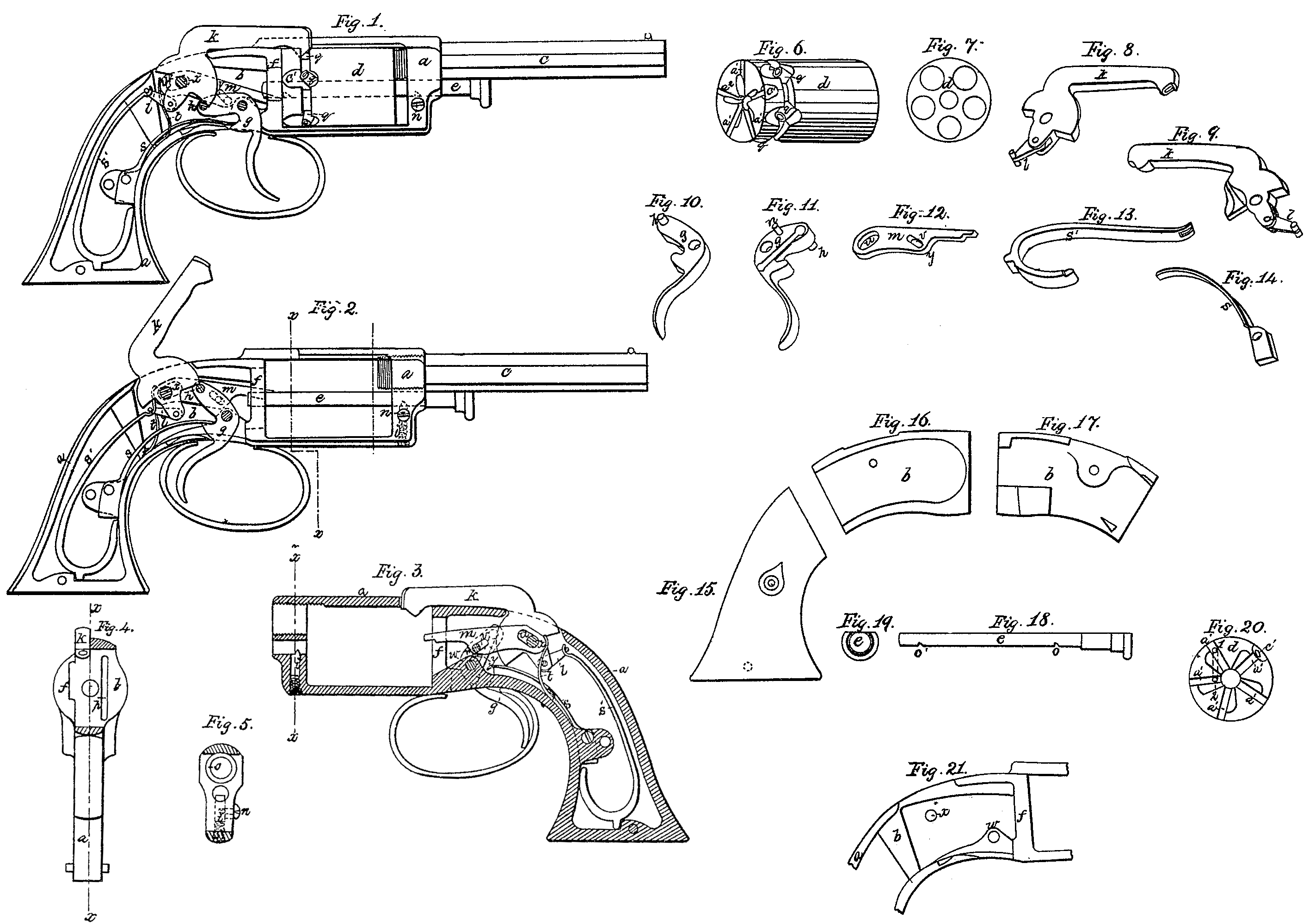
Figure 1 is a side view of the pistol constructed with my improvements, the casing of the handle and one side of the lock-plate being removed to exhibit the construction and arrangement of the several parts of the lock, which are in the position they occupy before the trigger is drawn back to fire the pistol. Fig. 2 is a similar view to Fig. 1, excepting that the rotating breech is removed and the parts of the lock are in the position they assume when the pistol is cocked and on the point of firing. Fig. 3 represents the lock frame and several parts of the lock in place in their position after the pistol is fired and before the trigger is allowed to recover its first position. This figure shows the side of the lock concealed from view in Figs. 1 and 2. Fig. 4 is a front view of the lock-plate through x x, Fig. 1. Fig. 5 is a sectional view of the lock-frame through x x, Fig. 3. Fig. 6 is a perspective of the rotating chambered breech. Fig. 7 is an end view of Fig. 6. Figs. 8 and 9 are perspective representations of the hammer and bridle. Figs. 10 and 11 are perspective representations of the trigger. Fig. 12 is the traversing lever. Fig. 13 is the mainspring. Fig. 14 is the trigger-spring. Fig. 15 is the casing of the handle. Fig. 16 is the movable side of the lock-plate. Fig. 17 is the reverse or inner side of Fig. 16. Fig. 18 is the arbor or axis on which the breech rotates. Fig. 19 is an end view of the head of Fig. 18. Fig. 21 is a side view of the lock-plate, showing the recess. Fig. 20 is a view of the rear ends of the rotating breech, showing the radial grooves.
In the several figures like letters of reference denote corresponding parts.
My improvements in rotating-breech fire-arms consist in the arrangement of the traverse-lever and its spring, so as to secure them from lateral derangement and permit of its playing on the same center as hammer; also, in the use of a cam in the lock-plate to withdraw the traverse-lever from the rotating breech when the trigger is not drawn back; also, the combination of the radial beveled grooves in the breech with the traverse-lever, for rotating and locking the breech when operated by the trigger of a trigger-cocking lock.
To enable others skilled in the art to make and use my improvements in fire-arms, I will proceed to describe more minutely the construction and operation thereof, and in so doing I shall of necessity refer to several parts of rotating-breech fire-arms, some of which are my invention and already secured to me by Letters Patent, and others are common to such fire-arms and need no particular description.
In the several drawings, a is the lock-frame, (shown in skeleton in Fig. 3.) b is the lock-plate. c is the barrel, screwed into the fore part of the lock-frame a. d is the revolving breech, which is inserted into the lock-frame and held in place by an arbor, e, of the shape shown in Fig. 18. This arbor passes through the fore part of the lock-frame a into the center of the recoil-shield f and forms the axis of the revolving breech.
The lock from a is open on both sides of the rotating breech to allow of its easy insertion or removal, so that by simply drawing out the arbor e the rotating breech is detached from the pistol. To prevent the accidental derangement of the rotating breech, the arbor e is kept in place by a spring-bolt, i, (see Figs. 2, 3, and 5,) inserted vertically in a hole bored in the fore part of the lock-plate. Around this bolt i is a spiral spring, which presses upward against the shank of the button n. The supper end of the spring-bolt i has a sharp beveled edge, which projects into the bore in the front of the lock-frame, through which the arbor e passes. The arbore has two notches, o o’, and the beveled edge of the spring-bolt i slips into the notch o when the arbor is passed through the rotating breech and into the notch o’ when the arbor is drawn out to release the rotating breech. To withdraw the arbor e the button n must be pressed downward, which causes the spring-bolt i to recede from the notch o.
The barrel c is screwed into the fore part of the lock-frame, so as to come in contact with the breech d, the bore of the barrel ranging with the bores or chambers in the rotating breech d.
The trigger g is pressed forward by the trigger-spring s, and has a cocking-arm furnished with a vibrating stud, h, operating on the toe of the hammer k, in combination with the beveled edge of the hammer, in the manner described in the specification of my patent of August 1, 1851.
s’ is the mainspring, acting on the heel of the hammer by the intervention of the bridle l in the usual manner.
In the lock-plate b (see Fig. 21) is a recess deeper than the plane in which the hammer and trigger work, in which is placed the traverse-lever n and hair-spring t. The shape of this traverse-lever is shown in Fig. 12. It works in the same center as the hammer k, the hammer-pin x passing through the Oval slot u. The extremity of the traverse-lever m is a rounded point, which projects through a long groove, p, (see Fig. 4.) in the face of the recoil-shield at the forward end of the lock-plate b, so as to enter the transverse radial grooves in the rear end of the rotating chambered breech d. A pin, r, (see Fig. 11) projects from one
side of the trigger and enters the small slot v (see Fig. 12) in the traverse-lever m, which, as the trigger is drawn back, raises the point of the traverse-lever m, causing it to turn on its center at a. The point of the traverse-lever m is pressed forward so as to project into the radial grooves in the rotating breech by the hair-spring t, which rests against it, back of the center-pin x, as seen at Fig. 2, when the trigger is drawn back and the hammer raised; but when the trigger is pressed forward in the position shown in Fig. 1 the traverse-lever m is pressed back so that its point recedes into the recoil-shield by means of a cam-like projection, w, in the lower part of the recess in the lock-plate, (see Fig. 21). which comes in contact with the shoulder y of the traverse-lever m, and will not allow it to descend without pushing it back, the slot u being of such length as to allow its backward motion over its center-pin x. Thus the point of the traverse-lever, on the reaction of the trigger g after firing, is drawn backward out of the radial groove a’ in the rotating breech, which allows it to pass over the edge of one groove, so as to enter the next groove a^2 when the trigger is again drawn back for repeated action, as hereinafter explained; and when the trigger is in the position shown in Fig.1 the point of the traverse-lever, having receded into the recoil-shield, no longer interlocks With the radial grooves in the rear end of the rotating breech, and offers no impediment to its free rotation on its axis or arbor.
The grooves a’ a’. &c., at the rear end of the rotating breech are equal in number to the chambers in the breech, and radiate from the center of its circumference. One side of each of these grooves is straight. The other side is chamfered off toward the center of the breech; but at the circumference both sides are straight, forming a narrow groove, into which the point of the traverse-lever m fits closely. The action of the traverse-lever an in these radial grooves a’ a’, &c., is as follows: As the trigger is drawn back the traverse-lever is raised above the cam in the recess of the lock-plate, and the hair-spring t presses forward the point of the lever m until it enters one of the radial grooves a’. As it rises farther, by the drawing back of the trigger g the point of the lever m presses against the straight edge of the groove and causes the breech to rotate on its arbor e until the point of the lever reaches the top of the groove, which is so situated in relation to the chambers of the breech as to bring one of them in exact range with the barrel of the pistol immediately before the fall of the hammer, and as the groove is close at the circumference of the breech the point of the lever m holds the breech d firmly in place and prevents its rotation so long as the trigger is held back. When, however, the trigger is released and resumes its first position the point of the traverse-lever m also falls, not, however, in the path of the groove a’; but being drawn back, as before explained, it passes over the chamfered edge of the groove a’, in which it has been engaged, and, leaving it, recedes into the recoil-shield. When next the trigger is drawn back the point of the traverse-lever an enters the rotating breech d, not in the groove it had left, but on the straight edge of the next groove, a^2. This action will be better understood by reference to Fig. 20, where 1 indicates the position of the point of the lever m when the pistol is fired, and the dotted lines indicate the path of the lever on its descent when the trigger is released, and 2 indicates the point in the next groove where the point of the lever enters when the trigger is again drawn back for repeated fire.
In order to prevent the possibility of the accidental discharge of the pistol, which might occur when the hammer rests on the percussion-cap on one of the nipples of the rotating breech, I make one or more notches, c’, in the circumference of the rotating breech a, between two of the nipples q q, in which notches c’ the edge of the hammer is made to enter. When the hammer rests in any one of these notches it is impossible that it should come in contact with any of the nipples q of the rotating breech d without the trigger is drawn back a considerable distance; and this arrangement does not interfere with the prompt action of the pistol, as it requires no adjustment to prepare it for use, for as soon as the trigger is drawn back to the point of the traverse-lever it enters its proper groove and brings one of the chambers of the breech in range with the barrel at the moment of firing with unerring certainty.
The hammer k of my pistol is not placed, as is usual in fire-arms, with the center of the hammer in a vertical plane passing through the axis of the barrel c and breech d, but it is so placed that one side of the hammer is in that plane, as will be seen by reference to Fig. 4, where x x is in the plane of the axis of the barrel, and k represents the end of the hammer. The object of this arrangement is not only to prevent the hammer being an obstruction in taking aim before firing, as is usually the case in trigger-cocking fire-arms, but the side of the hammer k, being exactly in the plane of the axis of the barrel, it forms a straight edge to sight by, thus giving increased facility for talking accurate aim.
In the specification and the accompanying drawings I have described my improvement as applied to a pistol; but it is equally applicable to all kinds of fire-arms in which rotary breeches are used.
Having thus described my improvement in revolving fire-arms, what I claim as my invention, and desire to secure by Letters Patent, is—
1. The arrangement of the traverse-lever to permit of its playing on the same center as the hammer without danger of lateral derangement.
2. The use of the cam in the lock-plate in combination with the shoulder on the traverse-lever for the purpose of withdrawing the point of the traverse-lever from the radial grooves in the rotating breech in the reaction of the trigger, for the purposes herein before set forth.
3. I do not claim the radial grooves in the end of the rotary breech as new in themselves; but I do claim the combination of radial beveled grooves in the rear end of-the-rotating breech with the traverse-lever, as applied to trigger-cocking fire-arms, for the purpose of rotating and locking the breech preparatory to firing, substantially as herein before described.
JOSIAH ELLS.
Witnesses:
Geo. M. Reed,
Fred. McMaster.