
Britain 4302
A.D. 1880, 21st October. № 4302.
Locks for Fire Arms.
LETTERS PATENT to Michael Kaufmann, of No. 11, Wellington Street, Strand, London, in the County of Middlesex, for an Invention of “Improvements in Locks for Fire Arms.”
PROVISIONAL SPECIFICATION left by the said Michael Kaufmann at the Office of the Commissioners of Patents on the 21st October 1880.
Michael Kaufmann, of No, 11, Wellington Street, Strand, London, in the County of Middlesex. “Improvements in Locks for Fire Arms.”
My Invention relates to certain improvements in locks for fire arms.
My improved lock will consist of five pieces, namely, the hammer, the trigger, the lifter, the central lever, and the mainspring.
The mechanism of this lock is extremely simple and substantial, and so constructed that, whilst the hammer wields an increased force in its descent on the cartridge, the pull of the trigger for arming the weapon is greatly decreased, and the return of the parts of the lock to their normal position is sure and brisk.
The central lever is of the most simple construction, and consists of a plain steel bar, pierced with a hole, which pivots on the axle of the hammer, and which, in combination with the main spring, controls the adjustment of the mechanism of the lock.
The mainspring is strong and substantial. The arm of the lower branch of the mainspring is constructed so as to be suspended on the top of the central lever and near to its axle, and this arm, near its extremity, is countersunk underneath to about the extent of the thickness of the central lever which passes under the said arm. The end of the lower branch of the spring which produces the rebound I make of considerable thickness, and extend it downwards so as to facilitate the rebound of the hammer, the two branches of the mainspring being, when at full cock, brought closely together so as to give its full force to the blow of the hammer on the cartridge.
SPECIFICATION in pursuance of the conditions of the Letters Patent filed by the said Michael Kaufmann in the Great Seal Patent Office on the 20th April 1881.
Michael Kaufmann, of No. 11, Wellington Street, Strand, London, in the County of Middlesex. “Improvements in Locks for Fire-arms.”
My Invention relates to certain improvements in locks for fire-arms,
The mechanism of my improved lock is simple and substantial, and having only one strong spring is durable. This lock is easily taken to pieces and put together, no screws being used.
The parts to which attention is principally drawn are:—
1st. The central lever, its important functions, and its simplicity of form, being easy to manufacture, quickly made, and at little cost.
Secondly. The mainspring, simple and strong, formed with a projection at the point producing the rebound.
The chief features are:—
1st. That the hammer is rebounding, actuated by the single spring in the mechanism of the lock, the spring being so constructed as to facilitate the rebound of the hammer to its place of rest.
Secondly. That the above feature permits the spring to be adjusted in such a manner that, when the hammer is at full cock, the branches of the spring are brought very closely together, so that the hammer wields an unusual degree of force in its descent on the cartridge, whilst the central lever acts with a minimum pressure on the-lifter-in order that, when used as a self-cocker, the weapon may be armed and fired by a very slight pull on the trigger.
Thirdly. That, combined with the above-mentioned advantages, the return of the 25 trigger and the other parts of the lock to their normal position after each fall of the hammer is sure and brisk.
This Invention is adapted for use in any kind of percussion fire-arm, but is especially applicable to revolvers.
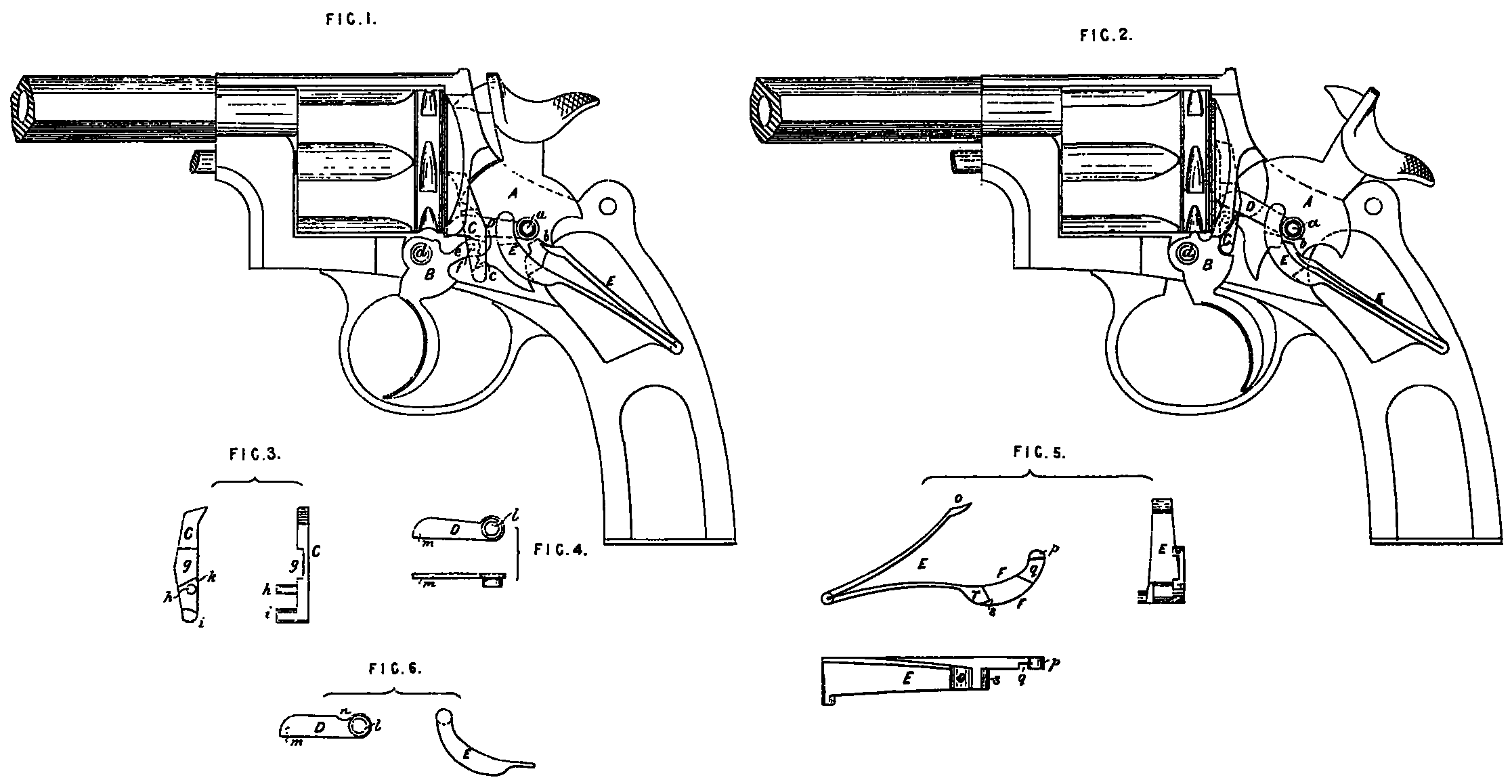
The accompanying Sheet of Drawing shows a revolver embodying my improvements.
Figure 1 being a side view or elevation of the revolver, the side plate being a removed, showing all the parts of the lock in their respective places, the hammer resting in its normal position.
Figure 2, a similar view, the hammer being at full cock.
Figure 3 is a front and side view of the lifter.
Figure 4, a side view and plan of the central lever.
Figure 5 shews the main spring in side, end, and plan view, and
Figure 6 illustrates a modification of the central lever and main spring.
Similar letters indicating similar parts in each of the Figures respectively.
A indicating the hammer.
B, the trigger.
C, the lifter.
D, the central lever.
E, the mainspring.
F, the arm of the lower branch of the mainspring.
The frame of the weapon is provided with two studs or pivots, the one for the hammer and central lever, and the other for the trigger. The hammer A is provided with the ordinary point for exploding the cartridge. A hole is formed in it for the central pivot a, and on the rear side of the hammer is formed a bearing b, for the mainspring. On the forward side of the hammer is projection c, having a notch for engagement with the trigger when the hammer is thrown back by the thumb, the said projection serving also for self-cocking the weapon.
The trigger B is perforated at d for the insertion of the pivot, A projection e, perforated at f for the pivot of the lifter, has a tooth or catch adapted to engage 5 with the notch on the projection of the hammer. The lifter C consists of a flat steel bar countersunk on one side, as shown at g, and provided with a pivot h, adapted to enter the hole f in the trigger.
A lug i projects from the lower end of the lifter, subserving the double function of locking and self-cocking the hammer. On the lower end or bottom of the countersunk part at k the central lever rests.
The central lever D is of the most simple construction, and consists of a steel bar pierced with a hole l for the hammer pivot a, The part m rests on the lifter at k, and holds it in proper position. The top of the bar at the end near the pivot or axle hole l, and where the end of the lower branch of the mainspring rests, should be slightly above the centre of the hole l, and may be a plane surface, as at Figure 4, or have a curve or recess as at n, Figure 6.
The mainspring E consists of two branches, the upper branch at o engages with the hammer at b. The lower branch is made strong and substantial, and constructed so that the end p of the arm F may be suspended on the top of the central lever and near to its axle at m, and this arm F near its extremity is countersunk underneath at g to about the extent of the thickness of the central lever, which passes under the said arm. The end or part of the lower branch of the spring I make of considerable thickness, and extend it downwards at s, producing at this point a safety stop with increased leverage, which produces the rebound of the hammer with facility, the two branches of the main spring being, when at full cock, brought closely together so as to give its full force to the blow of the hammer.
If I prefer to use a central lever D, having a plane surface, as at Figure 4, the end p of the arm F of the mainspring will have a flat surface to rest on the central lever. But where] find it preferable to use a central lever having a curve or recess at at n, Figure 6, I make that part of the main spring which is to rest therein with a similar curve, as also shown at Figure 6.
The operation of the lock is as follows:— Upon cocking the weapon by the thumb the projection of the hammer, which lies between the lifter and the trigger, engages with the latter, which carries up the lifter and with it the central lever D, thereby compressing the mainspring E, and at the same time effects the rotation of the cylinder, Finally, the tooth or catch in the trigger falls into the notch of the projection of the hammer, and the weapon is full cocked, as shown at Figure 2.
When the trigger is retracted the projection of the hammer comes out of engagement with the trigger, and the hammer is released and falls. Upon releasing the trigger the pressure of the mainspring delivered through the medium of the central lever acting upon the lifter carries the trigger forward and the lifter downward until its lug passes the projection of the hammer, when the pawl tilts forward and, coming under the said projection, locks the hammer, as shown in Figure 1.
In consequence of the formation of the central lever D, as above described, and the arm of the lower branch of the mainspring being suspended very close to and at a higher elevation than the centre of the axle of the said lever, upon releasing the trigger an increase of force is obtained, whereby the return of the parts to their normal position is certain and rapid, whilst very little power is required for the trigger-pull in self-cocking the weapon.
Coincidently with the descent of the lifter, the safety-stop e of the main-spring coming to bear upon the tail of the hammer effects the rebound of the hammer. In this position the hammer is positively locked, and no accidental discharge of a cartridge can take place.
It will be seen that in consequence of the increased thickness of the lower branch of the main spring at r, not only is the spring very substantial, but its extension downwards at s, increasing the distance from the axle of the hammer to the point of contact of the spring on the hammer, gives a great amount of leverage and enables the rebound of the hammer to be effected without great force from the action of the spring; this also permits the branches of the spring to come closely together so as to give its maximum force of blow to the hammer.
From the foregoing description it will be evident that the lock is double acting, and when used as a self-cocker the operation may be briefly described as follows:—
The trigger being retracted lifts the lifter, and its lug engages with the projection of the hammer, which is thereby raised until the lug passes from under the projection, when the hammer being released falls. During the lifting of the lifter it rotates this cylinder in the usual way, and at the same time the lifter, carrying with it the central lever, compresses the main spring, the lower branch of which bearing the safety stop being then sufficiently raised it does not impede the fall of the hammer, After the descent of the hammer the trigger is released, when the rebound and locking of the hammer is effected, as already described.
Having now described and ascertained the nature of the said Invention, and in what manner the same is or may be performed,
I claim as secured to me by the hereinbefore in part recited Letters Patent,—
Firstly. In a lock for fire-arms a main spring, as described, for the purpose of effecting the rebound of the hammer, and actuating the trigger through the medium of a central lever, substantially as set forth.
Secondly. In a lock for fire-arms, a central lever, as described, bearing upon the lifter and actuated by the mainspring in the manner substantially as set forth.
Thirdly. A lock for fire arms, as shown in the accompanying Drawings, and operating substantially as hereinbefore set forth.
In witness whereof, I, the said Michael Kaufmann, have hereunto set my hand and seal, this Twentieth day of April, in the year of our Lord One thousand eight hundred and eighty one.
MICHAEL KAUFMANN. (L.S.)
Witness,
W. E. Gedge,
Patent Agent,
11, Wellington St., Strand,
London.