
Britain 189
A.D. 1884, 1s January, № 189.
Improvements in Fire Arms.
PROVISIONAL SPECIFICATION.
I Michael, Kaufmann, of № 8 Devonshire Road, Greenwich, in the County of Kent, Gentleman, do hereby declare the nature of my invention for Improvements in Fine Arms to be as follows:—
My object is to provide a solid frame revolver with a device for the purpose of facilitating the rapid extraction of discharged cartridges by causing the cylinder to be self-rotating each time the rod-extractor is used in order to eject the cartridges or cartridge cases, and also with a device for the purpose of effecting the double locking of the cylinder with simply one locking arrangement, the cylinder being provided with only one set or series of stops, notches or holes.
I propose to construct a cylinder having in its interior a click actuated by a spring or similar contrivance to be operated by the axle passing through the said cylinder.
I propose to provide the axle with a number of teeth, pinions or ratchet corresponding in number with the number of Cartridges the cylinder will take. When the axle is put through the cylinder and is in its normal position, one of the teeth, pinions or ratchet of the axle will engage with the click in the interior of the cylinder.
I may modify this part of the device and provide the part of the axle passing through the cylinder with a click and spring which will engage with the teeth, pinions, ratchet or other suitable contrivance to be provided in the interior of the cylinder.
I propose to provide the axle near its end close in position to the rod-extractor with a series of teeth, cogs, cogwheel or other suitable contrivance to be operated by a rotary instrument also provided with a series of teeth, cogs, cogwheel or other suitable contrivance.
The rotary instrument is also provided with a projection which enters a slot in the rod-extractor or otherwise so connected with the rod-extractor that when the said extractor is being pushed for the purpose of ejecting a cartridge or cartridge case, the extractor carries with it for a certain distance the projection of the rotary instrument.
The rotary instrument when operated by the rod-extractor, rotates the axle and thereby rotates the cylinder, so that the cylinder is in a manner self-rotating, thus obviating the necessity of its being turned by the hand each time the rod-extractor is used for the purpose of ejecting a cartridge.
I propose also to provide the cylinder externally with only one set or seeies of notches or holes. Fitted in the frame of the Weapon, I provide an Arm, Stop-piice or bar suitably shaped, having an almost vertical or straight up and down action, actuated by a spring. One end of the Arm, Stop-piece or bar engages with the series of notches or holes in the cylinder for the purpose of holding the cylinder in position both when the Weapon is at full-cock and when the hammer is at the rebound or half-cock. At or near the other end of the Arm, Stop-piece or bar, I provide a projection or tailpiece which engages with a bearing with which the trigger is provided. On drawing the triggers back in order to discharge the Weapon, the bearing of the trigger engages with the projection of the Arm, Stop-piece or bar and pushes it down, thereby disengaging the said Arm Stop-piece or bar from one of the notches or holes of the cylinder in order to permit the cylinder to rotate.
The trigger continuing in its action for the purpose of discharging the Weapon, the bearing of the trigger disengages itself from the projection of the Arm, Stop-piece or bar and the latter being berated is forced back, actuated by the spring, towards the cylinder, and the one end of the Arm, Stop-piece or bar engages with one of the series of notches or holes of the cylinder as soon as the cylinder has completed the portion of its rotation which each complete action of the trigger effects.
The Arm, Stop-piece or bar in this position holds the cylinder securely, whilst the hammer is at full-cock, whilst being fired, and whilst~the trigger and other parts of the lock return to their normal position, that is, the Arum, Stop-piece or bar keeps the cylinder securely locked, both before and after the Weapon has been fired until the mechanism of the lock is again put into motion for the purpose of discharging a fresh cartridge.
I may modify the means by which I effect the double locking of the cylinder with simply one locking arrangement the cylinder being provided with a single series of notches or stops.
I may for instance provide an arm or stop-piece of suitable shape, hinged or otherwise, fitted in the frame of the Weapon in a position horizontal to the cylinder, having a swing action forming a segment of a circle, operated by the trigger and actuated by a spring for the purposes and in the manner described.
I may also provide the cylinder with a series of stops or projections and provide the Arm, Stop-piece or shaped bar with a hole or opening to engage with the stops or projections of the cylinder.
Or in the place of an Arm, Stop-piece or shaped bar, I may use a suitably shaped spring to be operated by the trigger for the purposes described.
Although specially applicable to solid frame revolvers, my invention or either part of the same may be applied to other descriptions of revolvers and revolving firearms.
Dated this first day of January 1884.
MICHAEL KAUFMANN.
COMPLETE SPECIFICATION.
I, Michael Kaufmann, of 8 Devonshire Road, Greenwich in the County of Kent, Gentleman do hereby declare the nature of my invention for “Improvements in Fire-Arms” and in what manner the same is to be performed, to be particularly described and ascertained in and by the following statement:—
My Invention is applicable to every description of revolvers or revolving small-arms, but when applied to solid frame or rod-extracting revolvers, it is necessary to employ also my patented moveable shield or hinged covering-plate No 3913, AD. 1881, for the purpose of liberating the cylinder in order to load or extract the empty cartridges.
My object is to provide a revolver or revolving small-arm with a device for the purpose of effecting the double locking of the cylinder with simply one locking arrangement, the cylinder being provided with only one set or series of lugs, notches or grooves.
I attain my object by providing an Arm or Stop-piece which I call a continuous Automatic Stop, fitted in the frame of the weapon, and by providing a trigger adapted to engage with the said stop-piece, as hereinafter fully described.
The advantages of my continuous Automatic Stop are as follows:—
1. It is self-acting, and keeps the cylinder securely locked when not in action, thereby preventing the danger of having unconsciously a discharged cartridge in line with the barrel through the.accidental rotation of the cylinder.
2. It effectively and independently keeps the cylinder in position at the time the weapon is being fired and is continuous in its action; that is, without the aid of the pawl, trigger or any other part of the lock, my Automatic Stop keeps the cylinder continuously securely locked, at the time the hammer is at full-cock, whilst 25 being fired, whilst the trigger and other parts of the lock return to their normal position, and until the mechanism of the lock is again put into motion for the purpose of discharging a fresh cartridge.
3. It obviates the wear or deterioration of the ratchet-wheel of the cylinder, produced by the usual friction of the lifter or pawl, for the purpose of aiding to 30 keep the cylinder in position whilst firing; this detrimental wear or deterioration of the ratchet-wheel being avoided, in consequence of my continuous Automatic Stop dispensing with the necessity of the said action of the lifter or pawl, on the ratchet-wheel of the cylinder.
4, It renders unnecessary the customary spring inserted in the tube or rod on which the cylinder revolves.
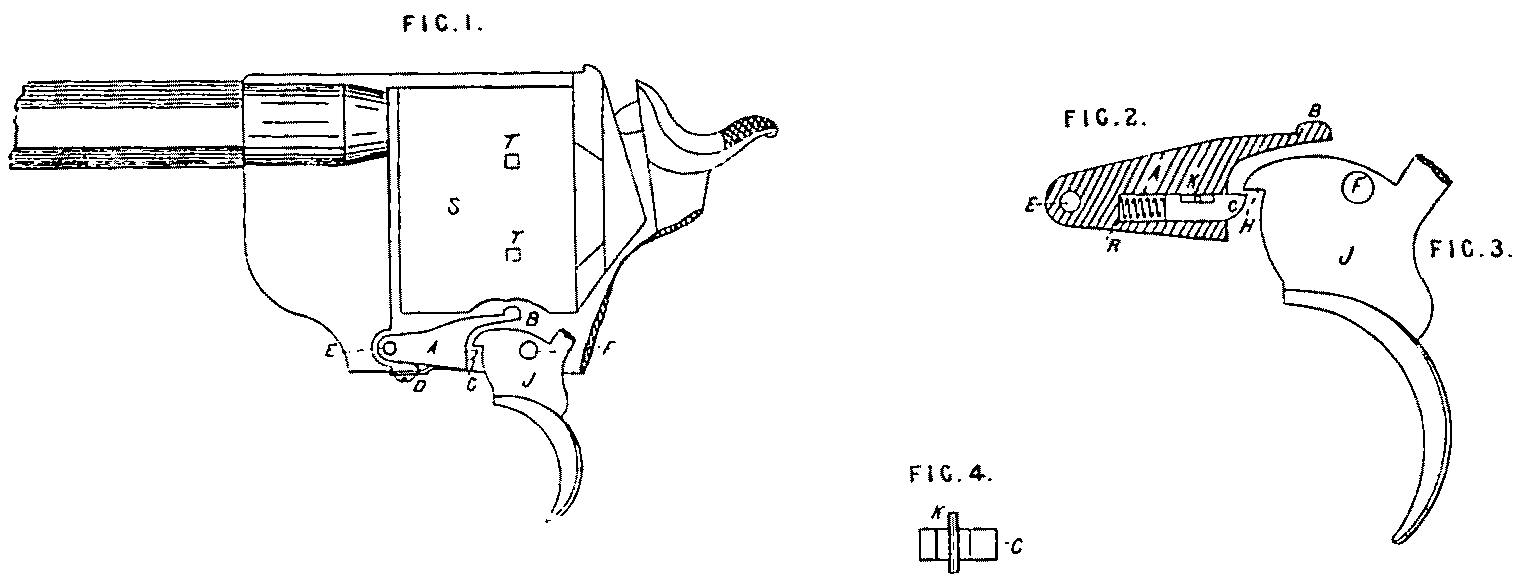
I will now proceed to describe my Invention, reference being had to the accompanying drawings.
Figure 1. is a section of a revolver showing the cylinder S, Trigger J, and Stop-piece A, in position, with a spring D, acting on said Stop-piece.
Figure 2. is an enlarged view of the Stop-piece A, showing. the rod or piston C, actuated by the spiral spring R, restricted in its motion and held in place by the pin or screw K.
Figure 3, is an enlarged side elevation of the trigger.
Figure 4, is an enlarged plan of the rod or piston C, showing the pin K.
The cylinder S, fig 1, is provided with a single series of grooves T.
The Trigger J, figᵃ 1 and 3, pivots on its axle F, and is provided with a bearing or projection H, adapted to engage with the end of the rod or piston O, forming a projection of the Stop-piece A.
The Stop-piece or continuous Automatic Stop A, figs 1 and 2 pivots on its axle E, and is provided with a stop B, adapted to enter either of the grooves T, on the cylinder S, and is also provided with a groove adapted to receive the rod or piston C, and the spring R, as shown in fig 2.
The Rod or Piston C, figᵇ 2 and 4, is provided with an opening or slot to receive the pin or screw K, and is actuated by the spring R.
The pin K, is inserted in the Stop-piece or continuous Automatic Stop A, passing through the slot or opening of the Rod or Piston C, in order to keep the Rod or Piston C, in place and to limit the action of the Rod or Piston C, when actuated by the spring R, or the Trigger J.
The spring D, actuates the Stop-piece A, and keeps it in position.
The operation is as follows:—
On operating the trigger for the purpose of firing the weapon, the bearing or projection H, of the trigger J, engages with the end of the rod or piston C, forming a projection of the Automatic Stop A, and the Automatic Stop A, turning on its pivot E, its Stop B, is withdrawn from one of the notches or grooves T, of the cylinder, permitting the cylinder to rotate.
As the trigger J, continues to be retracted, its bearing or projection H, disengages from the end of the rod or piston C, forming the projection of the Automatic Stop A, which being released, the Automatic Stop A, actuated by the spring D, returns to its normal position and the stop B, of the Automatic Stop enters one of the notches or grooves T, of the cylinder, as soon as the cylinder in its course of rotation has brought a fresh cartridge in line with the barrel. In this position, the Automatic Stop securely locks the cylinder and continuously keeps it locked, until the mechanism of the lock is again put into motion for the purpose of discharging a fresh cartridge.
Upon releasing the trigger, the bearing or projection H, of the trigger engages with the end of the rod or piston C, forming a projection of the Automatic Stop A, and forces back the whole of the rod or piston C, into the interior of the Automatic Stop A, permitting the trigger J, to return to its normal position without disengaging the stop B, of the Automatic Stop from the groove T, of the cylinder.
As soon as the bearing or projection H, of the trigger J, on its return to its normal position, is disengaged from the end of the rod or piston C, the spring R, forces forward the rod or piston C, until it again assumes its normal position forming a projection of the Automatic Stop A.
I may modify the above device by dispensing with the rod or piston C, and the spring R, making the Stop-piece A, of two parts, the one part containing the projection of the Stop-piece being pivoted at its upper end near the Stop B, and with a shoulder at its lower end so arranged that the spring D, shall perform the double function of actuating the return of the Stop B, of the Stop-piece to its normal position and of likewise actuating the return of the projection of the Stop-piece to its normal position, when the said Stop-piece is released from the trigger in its downward and in its upward action.
I may also modify my device by making the Stop-piece of one piece only, and making a groove in the trigger to receive a rod or piston forming a projection to the said trigger and actuated by a spiral spring, the whole actuating and for the purposes as described.
I may also modify my device by fitting in the frame of the Weapon, a continuous Automatic Stop having an almost vertical or straight up and down action actuated by a spring, the whole actuating and for the purposes as described.
I may also provide the cylinder with a series of stops or lugs and provide the Stop-piece with a bearing having a hole or opening adapted to engage with the stops or lugs on the cylinder.
I do not limit myself to the above modifications as there are other ways of modifying my device for the purposes described.
Having now particularly described and ascertained the nature of my said Invention, and in what manner the same is to be performed, I declare that what I claim is:—
First. In a revolving fire-arm, the continuous Automatic Stop or Stop-piece A, for the purposes specified,
Second. In a revolving fire-arm the Trigger J, adapted to engage with the continuous Automatic Stop for the purposes specified.
Third. In a revolving fire-arm, a cylinder provided with only one series of lugs, notches or grooves, combined with a trigger and Stop-piece for the purpose of effecting the double locking of the cylinder with simply one locking arrangement, as hereinbefore fully described and substantially set forth.
Dated this Thirtieth day of September 1884.
For the Applicant,
W. E. GEDGE,
Agent.