
US 212473
UNITED STATES PATENT OFFICE.
MICHAEL KAUFMANN, OF LONDON, GREAT BRITAIN, AND JULIEN WARNANT, OF BIOGNEE, BELGIUM; SAID WARNANT ASSIGNOR TO SAID KAUFMANN.
IMPROVEMENT IN LOCKS FOR FIRE-ARMS.
Specification forming part of Letters Patent No. 212,473, dated February 18, 1879; application filed January 10, 1879.
To all whom it may concern:
Be it known that we, MICHAEL KAUFMANN, of the city of London, Kingdom of Great Britain, and JULIEN WARNANT, of Hognée, Commune of Cheratte, Kingdom of Belgium, have invented certain new and useful Improvements in Fire-Arms; and we hereby declare the same to be fully, clearly, and exactly described as follows, reference being had to the accompanying drawings, in which–
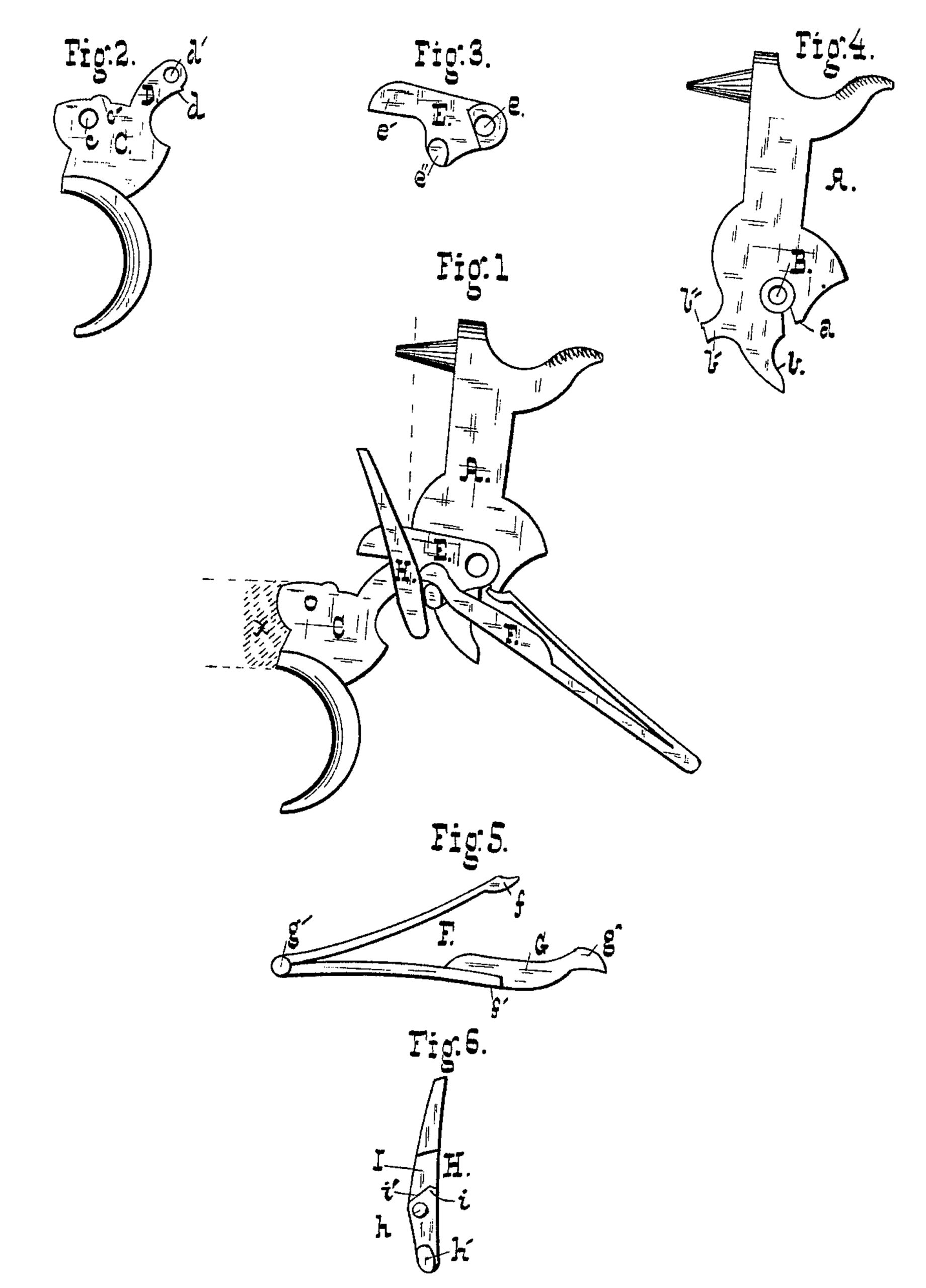
Figure 1 is a plan view of the lock complete; Figs. 2, 3, 4, 5, and 6, respectively, similar views of the trigger, arm, hammer, mainspring, and pawl.
Our present invention relates to locks for fire-arms, and, while it is adapted for use in any form of percussion fire-arm, it is especially designed to be applied to revolvers; and our said invention consists in certain improvements upon that described in Letters Patent of Great Britain, No. 3,206 of 1876, of the Kingdom of Belgium Nos. 38,328, dated December 15, 1875, and 39,792, June 30, 1876; also, in United States Patent No. 202,418, dated April 16, 1878, in which latter, in particular, the construction of the various parts of the lock is fully set forth.
Suffice it that the hammer, trigger, and pawl illustrated in the accompanying drawings differ in no wise from those described in the patents referred to, and their mutual adaptation and disposition in the lock are the same.
The trigger C is perforated at c for the pivot, has a lug, c’, for engagement with the cylinder when the weapon is full-cocked, and a projection, D, with the pawl-pivot hole d’ and notch d. The hammer A has a pivot-hole, B, lug b’, with notch b” to engage with the trigger, tail-piece b, and bearing a for the mainspring, shown and described in the patents referred to.
The pawl H is recessed at I, the bottom of the recess being formed in two inclines, i’, whose apex i is forward of the pivot h. The latter is adapted to enter the hole d’ in the trigger. A lug, h’, projects from the lower end of the pawl, subserving the double function of locking and self-cocking the hammer.
The mainspring F engages at f with the hammer, and its lower leaf, f’, serves to effect the rebound of the latter. Instead of engaging directly with the pawl, however, as in the patented invention, the arm G of the main spring terminates in a bearing, g, which engages with the arm E, that constitutes the salient feature of our present invention. This piece, which we term the “arm,” is represented in Fig. 3 of the drawings. It consists of a suitable piece of steel having a hole, e, for the hammer-pivot, a lug, e”, upon which the end g of the mainspring bears, and a projection, e’, which rests upon the incline i’ of the pawl.
It may here be remarked that all of the parts of the lock are drawn to a scale in the accompanying drawings, and are therefore of precisely the proper relative size and shape.
The piece or arm E subserves an important function in the lock; it equalizes the trigger-pull in self-cocking the weapon–a, most important end, if accuracy of aim may be considered an object–and it more efficiently regulates the bearing of the pawl upon the ratchet piece of the cylinder.
The operation of the lock is as follows: Upon cocking the weapon in the usual way, the lug b’ of the hammer engages with the end D of the trigger, which carries up the pawl, and with it the arm, compressing the main-spring. As the trigger is retracted the notches d b” come out of engagement and the hammer falls. Upon releasing the trigger the pressure of the mainspring, delivered through the medium of the arm and pawl, carries the trigger forward and the pawl downward until its lug h’ passes the projection b’ of the hammer, when the pawl tilts forward, owing to the arrangement of the bearing i’, and coming under the projection blocks the hammer. Coincidentally with the descent of the pawl, the end f’ of the mainspring coming to bear upon the tail-piece of the hammer effects its rebound. It is clear that the hammer cannot, by any possibility, be made to reach a cartridge without being first raised to full-cock, by reason of the bringing up of the trigger against the main frame x of the weapon.
It will have been made evident from the foregoing description of the parts, not only that the lock is double-acting, but also how it operates as a selfcocker, rendering a further description unnecessary.
When used in a fire-arm not a revolver, of course the pawl would be a superfluity, and might either be dispensed with entirely, the arm being made to bear upon a suitable projection on the trigger, or, if the self-cocking feature is desired, the pawl might be simply cut off just above its pivot for the trigger.
The arm is in effect a bent lever, and its operation in equalizing the trigger-pull depends upon the relative acting distances of the power and weight from the hammer-pivot.
What we claim as new, and desire to secure by Letters Patent, is–
1. In a lock for fire-arms, a mainspring adapted to effect the rebound of the hammer, and actuating the trigger through the medium of a pivoted connection, E, substantially as set forth.
2. The lock for revolving fire-arms herein described, consisting of hammer, trigger, pawl, arm, and mainspring, the latter serving to effect the rebound of the hammer and actuating all of the parts named, substantially as and for the purpose set forth.
MICHAEL KAUFMANN.
JULIEN WARNANT.
In presence of–
MATHIAS KURTH,
PIERRE HUSE.