
Britain 445
A.D. 1876, 3rd February. № 445.
Pistols.
LETTERS PATENT to William Robert Lake, of the Firm of Haseltine, Lake, & Co., Patent Agents, Southampton Buildings, London, for the Invention of “Improvements in Revolving Cylinder Pistols.” A communication from abroad by Edward Palmer Boardman, of Lawrence, Massachusetts, United States of America, Manufacturer.
Sealed the 12th May 1876, and dated the 3rd February 1876.
PROVISIONAL SPECIFICATION left by the said William Robert Lake at the Office of the Commissioners of Patents on the 3rd February 1876.
WILLIAM ROBERT LAKE, of the Firm of Haseltine, Lake, & Co., Patent Agents, Southampton Buildings, London. “Improvements in Revolving Cylinder Pistols,” A communication.
My Invention relates to that class of pistols generally known as revolvers, and consists in a novel construction and arrangement of the parts by which the size of the implement is greatly reduced while its effectiveness is increased.
It is well known that pistols of this nature when constructed with a stock or handle of sufficient proportions to enable them to be held in the hand and discharged in the usual manner without depending upon the barrel to steady the same, are too cumbersome to be conveniently carried in the pocket.
It is also well known that most pistols, whether revolvers or otherwise require cocking by an independent, or entirely different motion of the hand from that made in discharging the same, that is to say, the hammer is drawn back and set by one movement and the trigger pulled by another, thus rendering it impossible in many instances to fire as rapidly as desirable
My said Invention is designed to obviate this objection and difficulty, and to that end I make use of the following means:— The cylinder, which is of the ordinary construction, is arranged to revolve on the pintle or axis having the pull or head, and is provided with a series of cartridge chambers arranged parallel with each other and with the barrel in the usual manner. A lever is pivoted in the lower part of the stock, and to one end of this lever there is jointed the locking pin or bolt, working vertically in a hole in the stock, its upper end fitting into a groove cut around the pintle and into which it is forced by the expansive action of the coiled spring beneath the free end of the lever. Pivoted in a proper socket or cavity formed within the breech of the pistol there is a hammer provided with a spring, the expansive action of which tends to force the hammer in the direction of the cylinder. On the lower part of the hammer, contiguous to the cylinder, is a flange or projection, to which is pivoted a click or pawl provided with a spring. This spring has one of its ends attached to the interior of the stock, its opposite or free end resting upon the pawl and forcing it down into contact with a series of ordinary ratchet teeth arranged in circular form on the end of the cylinder.
A pin is fitted to work in a hole drilled vertically in the hammer, and beneath this pin there is a coiled spring the action of which causes it to protrude slightly above the top of the hammer forming a yielding stud or dog.
The stock is extended somewhat above the barrel and provided with a longitudinal aperture or hole in which the rod is fitted to slide freely in parallelism with the barrel, being kept from revolving by a projection on the outer end of the rod working in a groove or runlet formed on the upper side of the barrel.
The inner end of the rod is provided with a downwardly projecting tooth or stud, and the outer end is provided with the pull or finger piece which is pivoted therein. The outer end of the rod is also drilled to receive a short coiled spring, the inner end of which rests against the rod, and the outer end against the pulley, the action of the spring tending to keep the pulley in a vertical position.
Attached to the stock beneath the rod and arranged to extend over the cylinder is a flat spring provided upon its lower face with a stop or catch fitted to work in a series of depressions or nicks formed in the periphery of the cylinder and corresponding in number with the number of chambers therein. The trigger rod is provided with a spiral spring to force it outward when released
A boss on the trigger rod is so formed, and the aforesaid flat spring so arranged, that the boss elevates the said spring catch as the boss advances, until the hammer is nearly ready to strike, when the catch is released and permitted to fall into one of the nicks as described.
SPECIFICATION in pursuance of the conditions of the Letters Patent filed by the said William Robert Lake in the Great Seal Patent Office on the 3rd August 1876.
William Robert Lake, of the Firm of Haseltine, Lake, & Co., Patent Agents, Southampton Buildings, London. “Improvements in Revolving Cylinder Pistols.” A communication from abroad by Edward Palmer Boardman, of Lawrence, Massachusetts, United States of America, Manufacturer.
My Invention relates to that class of pistols generally known as revolvers, and consists in a novel construction and arrangement of the parts as herein-after more fully set forth and claimed, by which the size of the implement is greatly reduced, while its effectiveness is increased.
It is well known that pistols of this class, when constructed with a stock or handle of suitable proportions to enable them to be held in the hand and discharged in the usual manner without depending upon the barrel to steady the same, are too cumbersome to be conveniently carried in the pocket.
It is also well known that most pistols, whether revolvers or otherwise, require cocking by an independent or entirely different motion of the hand from that made in discharging the same, that is to say, the hammer is drawn back and set by one movement and the trigger pulled by another, thus rendering it impossible in many instances to fire rapidly.
My Invention is designed to obviate this difficulty, and to that end I make use of means the nature and operation of which will be readily understood from the following description.
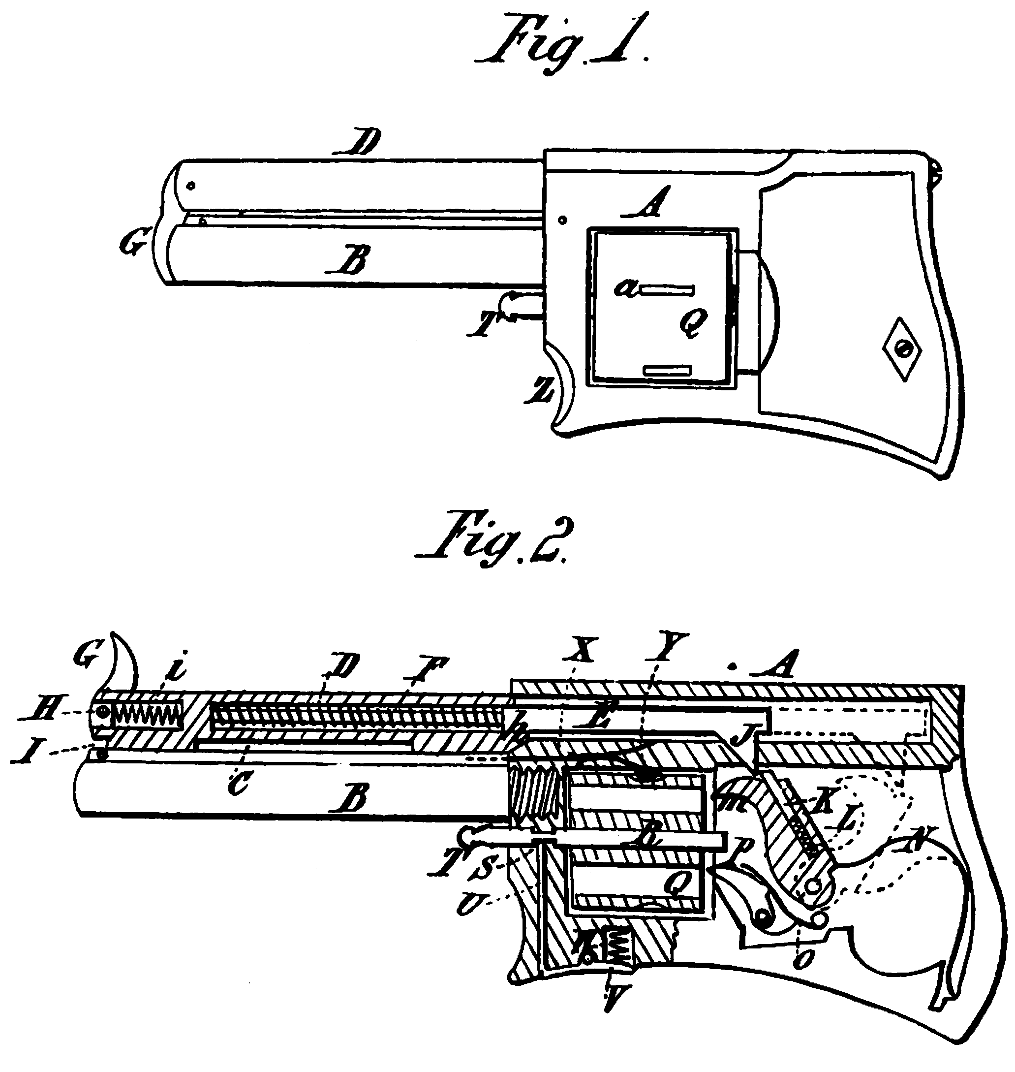
DESCRIPTION OF THE DRAWING.
Figure 1 is a side elevation, and Figure 2 a vertical longitudinal section of Invention.
Like letters indicate corresponding parts throughout the Drawing.
A is the stock or body; B, the barrel; Q, the cylinder; and D, the push pin or trigger rod. The cylinder, which is of the ordinary construction, is arranged to revolve on the pintle or axis R provided with the pull or head T, and is provided with a series of cartridge chambers arranged parallel with each other, and with the barrel B in the usual manner. A lever V is pivoted in the lower part of the stock, and to one end of this lever is jointed the locking pin or bolt U working vertically in a hole in the stock, its upper end fitting in a groove S cut around the pintle R and into which it is forced by the expansive action of the coiled spring W beneath the free end of the lever. Pivoted in a proper socket or cavity formed within the breech of the pistol there is a hammer m provided with a spring N, the expansive action of which tends to force the hammer in the direction of the cylinder Q. On the lower part of the hammer m, contiguous to the cylinder, there is a flange or projection to which is pivoted a click or pawl P provided with the spring O. This spring has one of its ends attached to the interior of the stock, its opposite or free end resting upon the pawl and forcing it down into contact with a series of ordinary ratchet teeth arranged in circular form on the end of the cylinder.
A pin K is fitted to work in a hole drilled vertically in the hammer, and beneath this pin there is a coiled spring L, the action of which causes it to protrude slightly above the top of the hammer, forming a yielding spring stud or dog.
The stock A is extended somewhat above the barrel B and provided with a longitudinal aperture or hole in which the rod D is fitted to slide freely in parallelism with the barrel, being kept from revolving by the projection I on the outer end of the rod working in a groove or rimlet C formed on the upper side of the barrel.
The inner end of the rod is provided with a downwardly projecting tooth or stud J, and the outer end with the pull or finger piece G, which is pivoted therein at H. The outer end of the rod is also drilled to receive the short coiled spring i, the inner end of which rests against the rod, and the outer end against the pull G; the action of the spring tending to keep the pull in a vertical position.
Attached to the stock beneath the rod D and arranged to extend over the cylinder Q there is a flat spring X provided upon its lower face with the stop or catch Y which is fitted to work in a series of depressions or nicks a formed in the periphery of the cylinder Q, and corresponding in number with the number of chambers therein.
In the use of this improved revolver the spring V is depressed, withdrawing the pin U from the slot S, thus enabling the pintle R and cylinder Q to be removed, when the cylinder may be charged or loaded with cartridges in the usual manner and again returned to its position. The pistol is then held in the palm of the hand, the end of the barrel B resting on the second finger, the forefinger being placed around the pull G, which should be elevated, as shown in Figure 2. The rod D is then pulled or forced inward, the tooth J being thus brought into contact with the pin K, pushing the hammer m back, and causing the pawl P to act against the ratchet on the cylinder R to revolve the same, the catch Y being in the mean time raised out of the nick a. As the rod D continues to advance and the cylinder to revolve the hammer m will be thrown back to full cock, when the tooth J will escape or pass by the pin K, leaving the spring N to force the hammer down upon the cartridge with a sharp percussive blow, and explode the same. Just prior to the tooth J passing or escaping the pin K as described, one of the loaded chambers in the cylinder will be brought into such a position that its axial or central line will be coincident with that of the barrel B, in which position it will be held by the stop Y falling into one of the nicks a, thus properly securing the cylinder before the discharge takes place. The rod D being now released the expansive action of the spring F will force it outward, causing the tooth J to pass over the pin K, the spring L yielding for that purpose, and thus bringing the parts again into the position shown in Figure 2, preparatory to firing another shot. The pull G serves not only as a finger piece with which to pull the rod D but also as a guard or stopper to prevent the entrance of foreign substances into the barrel B, as seen in Figure 1. The forward end of the stock is cut out or made concave at Z to enable the pistol to be held more securely by the finger on which the barrel is rested, as described. The boss h on the rod D is so formed and the spring X so arranged that the boss elevates the catch Y as the boss advances, until the hammer is nearly ready to strike, when the catch is released and permitted to fall into one of the nicks, as described. The hammer m being entirely concealed within the stock or breech, the pistol is in a great measure prevented from being accidently discharged after the manner of ordinary pistols.
It will be obvious that the spring F may be dispensed with by employing a ring attached to the rod D, and so arranged that the rod may be worked both ways by the finger inserted in the same without departing from the spirit of my Invention; also that the pull G may be either pivoted or rigid, as preferred.
Having thus fully described the said Invention, as communicated to me by my foreign correspondent, and the manner of performing the same, I wish it under stood that I claim,—
First. In and forming part of a pistol of the class above described, the sliding rod D and hammer m combined to operate, as above specified.
Second. The hammer m provided with the spring pin K, as above set forth.
Third. The spring F in combination with the rod D, as above specified.
Fourth. The pull G arranged to operate, as above set forth.
Fifth. The cylinder Q, barrel B, hammer m, pawl P, and rod D, combined to operate as above specified.
Sixth. The boss h in combination with the spring catch Y, as above set forth.
In witness whereof, I, the said William Robert Lake, have hereunto set my hand and seal, this Third day of August, in the year of our Lord One thousand eight hundred and seventy-six.
Wᵐ. ROBᵀ. LAKE (L.S)