
US 109914
UNITED STATES PATENT OFFICE.
CHARLES J. LINBERG AND WILLIAM J. PHILLIPS, OF ST. LOUIS, MISSOURI.
IMPROVEMENT IN REVOLVING FIRE-ARMS.
Specification forming part of Letters Patent No. 109,914, dated December 6, 1870.
To all whom it may concern:
Be it known that we, CHARLES J. LINBERG and WILLIAM J. PHILLIPS, of St. Louis, in the county of St. Louis and State of Missouri, have invented new and useful Improvements in Revolving Fire-Arms; and we do hereby declare that the following is a full, clear, and exact description thereof, which will enable others skilled in the art to make and use the same, reference being had to the accompanying drawing, forming part of this specification.
This invention relates to improvements in revolving pistols or other fire-arms; and it consists in mounting the barrel on an axis parallel with the axis of the cylinder in such a manner that the securing the barrel with the cylinder for firing and the releasing of the cylinder for loading are effected by swinging it sidewise in a manner better calculated for convenience in manipulating the arm than the present improvements.
The invention also comprises an arrangement of two cylinders, to be shifted on the spindle for being alternately used, said cylinders being provided with firing-pins, contained in one of the spaces between the chambers, and communicating the blow of the hammer through the rearmost to the caps on the one to be fired, placed at the front. The said cylinders are also arranged so that the caps are protected from wet and accidents by cavities in the bases, which meet together and form completely inclosed chambers when placed on the spindle with the ends having the caps placed together.
The invention also comprises an improved arrangement of operating-gear for revolving the cylinders, as hereinafter more fully described.
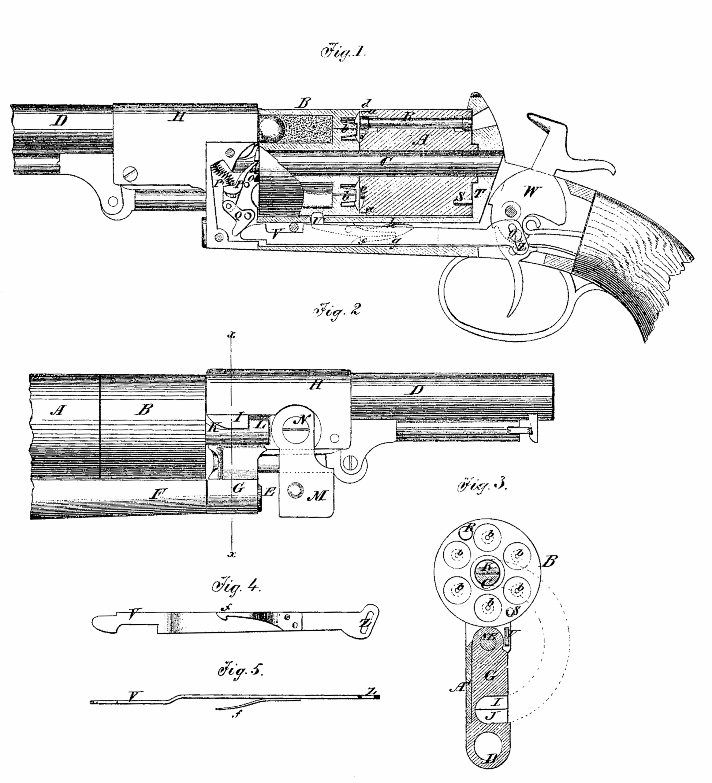
Figure 1 is a longitudinal sectional elevation of our improved revolving fire-arm. Fig. 2 is a side elevation of the same. Fig. 3 is a transverse section taken on the line x x of Fig. 2. Fig. 4 is a side view of the sliding bar and spring used for actuating the revolving cylinders, and Fig. 5 is an edge view of the same.
Similar letters of reference indicate corresponding parts.
A and B represent the cylinders, and C the spindle on which they are mounted. D represents the barrel. It is mounted on the pivot pin E, projecting from the end of the stock F below the chambers parallel with the spindle C, said pin passing through the strong arm G, projecting from the stock H of the barrel. This stock, which has a hollow cavity, J, at the under side, carries the shouldered piece I, which swings into the cavity K in the upper side of the spindle C, behind the shoulder L, and firmly locks the barrel against the tendency of the force of the discharge to throw it forward, and the bottom of the cavity J arrests the barrel when closing. The said barrel is held in the position against swinging back by the plate M, pivoted to the stock H at N, and swinging at the free end up past the ratchet-teeth O, which project slightly from the end of the cylinder, or it may bear against the side of the spindle C.
The cylinder B has a flange, d, projecting at its rear end flush with its periphery, and the cylinder A has a circumferential recess or rabbet, a, at its front end, for the purpose of receiving said flange.
The adjacent ends of the cylinders are cut out to form a chamber, e, for the nipples and caps, which is completely closed or shut in by the flange d.
Each cylinder is provided, in a longitudinal hole formed between two chambers, with a needle or rod, R, capable of a slight movement lengthwise, and arranged for receiving the blow of the hammer and communicating it to the cap in front of it to be exploded.
The cylinders are held, when placed at the rear, so as not to revolve, and that their needles will receive the hammer at the rear end by a pin, S, projecting from the seat T of the stock, for the rear ends of the cylinders into a hole suitably arranged in the end of each cylinder for it, and the front cylinder is held so that the caps for the respective chambers will be in front of the needle by the locking lever V.
The rotation of the front cylinder is effected by the pawl P, headed lever Q, and sliding bar V, the latter extending backward under the cylinders in a groove in the stock F to the hammer-arm W, to the side of which, below its pivot, it is connected by the stud-pin y, which passes through the oblique slot z in the said bar, and imparts a forward movement to it when the hammer is raised, throwing the frontend, which is beveled, under the one arm of the head of lever Q, which, being pivoted at the other arm, as shown at Q’, will force up the pawl P and turn the cylinder. The falling of the hammer draws the bar V back, and the spring P’ throws the pawl P back.
The pawl-lever Q and spring are arranged in a cavity in the arm G of the stock H at the side opposite to that on which plate M is, which cavity is covered by a thin plate, A’, which may be readily detached when access is desired.
The bar V and the lever Q are so arranged that when the hammer is on half-cock the point of contact between them coincides with the line of the joint between the barrel-stock H and the cylinder-stock F, so that when in this condition the barrel may be swung around to detach the cylinder.
The cylinder locking-lever u is thrown down at the moment the pawl P begins to act on the ratchet by the head of the spring f on bar V passing under the projection g on the lower end of lever U. This lever is thrown up again as soon as the spring f passes beyond projection g by the spring h, and the upper end is forced into the notch in the cylinder when the said notch arrives at the right position.
When the bar V moves back the head of lever f passes head g at the side, the latter being suitably beveled on one side to allow the former to go back again without catching.
By the employment of the two cylinders, which are shifted when one has been exhausted, the empty one being placed at the rear and the other at the front, the capacity of the arm is doubled, and it may be further increased by the employment of any number of extra cylinders, all fitted alike, to apply loaded ones as the others are discharged, the said extra cylinder being carried in holsters suitably adapted for the purpose, or in any other convenient way.
By the employment of two cylinders a better distribution of the weight of the arm is secured, for, the weight being more distant from the hand, the latter is more sensitive to its influence in bringing it to the eye and holding it there than when the weight is nearer.
The arrangement of the two cylinders at the ends which meet together insures protection to the caps from wet or accident.
We propose to make the cylinders so that they may either be used for firing caps with powder and ball or cartridges by making the nipples to screw into the rear ends of the chambers, so as to be put in when firing with caps, and be taken out to use cartridges.
Having thus described our invention, we claim as new and desire to secure by Letters Patent–
1. The barrel-stock, pivoted on an axis parallel with the axis of the cylinder, for opening to disengage the cylinders, and having the cavity in the side for receiving the spindle C when closing with the cylinders, all substantially as specified.
2. The locking-plate M, arranged with the barrel-stock H and the projecting ratchet teeth O, substantially as specified.
3. The two cylinders arranged in connection for alternate use, and provided with the in closed needles R., arranged and operating substantially as specified.
4. The annular nipple-chamber e, formed by the grooves or recesses in the adjacent end of the cylinders A and B, and closed by the flange d, fitting in recess a, as shown and described.
5. The turning-pawl P, lever Q, bar V, and hammer-arm, all combined and operating substantially as specified.
6. The combination, with the locking-lever U, having the beveled head h and slide-bar V, of the headed spring f, all substantially as specified.
CHARLES J. LINBERG,
WILLIAM J. PHILLIPS.
Witnesses:
DAVID RODEN,
G. FITZGIBBONS.