
US 48775
UNITED STATES PATENT OFFICE.
LOUIS C. RODIER, OF SPRINGFIELD, MASSACHUSETTS, ASSIGNOR TO SAMUEL NORRIS, OF SAME PLACE.
IMPROVEMENT IN REVOLVING FIRE-ARMS.
Specification forming part of Letters Patent No. 48,775, dated July 11, 1865.
To all whom it may concern:
Be it known that I, Louis C. Rodier, of Springfield, in the county of Hampden and State of Massachusetts, have invented certain new and useful Improvements in Fire-Arms; and I hereby declare that the following is a full, clear, and exact description of the same, reference being had to the accompanying drawings, in which—
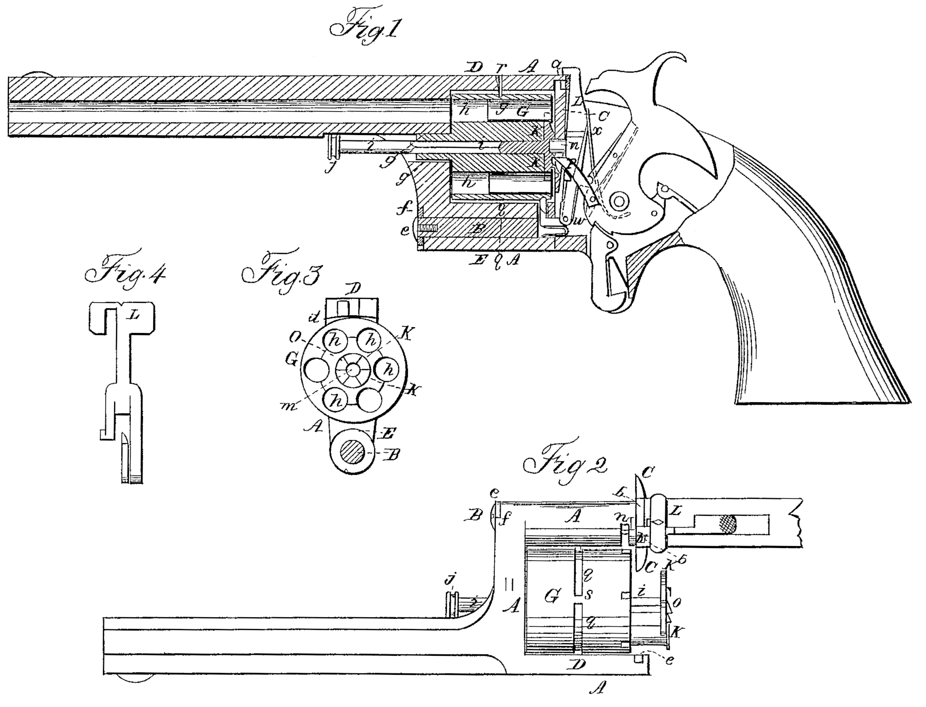
Figure I is a vertical section of a pistol constructed in accordance with my invention, the plane of section passing through the center or axis of the barrel, and showing in elevation the trigger, hammer, and the other parts of the mechanism for operating the cylinder. Fig. 2 is a plan view of the pistol in position when the cartridges or exploded cartridge-cases are being withdrawn from the cylinder. Fig. 3 is an end view of the cylinder, looking toward the barrel; and Fig. 4 is a detail view of the spring lever or catch for holding the cylinder in place.
My invention relates to that class of fire-arms in which a many-chambered cylinder is arranged for repeating action. Most of those heretofore constructed involve the revolving principle— i.e., the combination, with the lock and its appurtenances, of a mechanism which actuates the cylinder to move continuously in one direction the distance of one chamber at every cocking of the arm, This has been found to be a source of deception as to the condition of the arm, and often of danger, because the cylinder will continue to revolve and the parts with which it is combined to operate as though all the chambers are loaded, when, in fact, all or some of the charges may have been fired, and thus the arm may fail when greatest reliance is placed upon it. It has also been found dangerous to ascertain the condition of such fire-arms, inasmuch as the arm for that purpose is necessarily held pointed toward the face of the party inspecting it, and many accidents are recorded from this cause.
To obviate these objections the first part of my invention consists, first, in the arrangement of a repeating fire-arm having a many chambered cylinder hung upon a central axis in such manner that the said cylinder shall revolve or oscillate between two given points— i. e., between the first and last chamber; second, in combining with an open frame provided with a projecting stud a cylinder movable upon it axis, and grooved between two points of its circumference, so as to allow of its revolution or oscillation, as hereinafter set forth, or, vice versa, in combining with an open frame a cylinder movable upon its axis, provided at two points of its circumference with one or two projecting studs, substantially as hereinafter described.
The second part of my invention relates to the withdrawal of cartridges or the metallic shells of fired cartridges, and consists, first, in providing the retractor on the end of the sliding pin, when located in the rear of the cylinder, with ratchet-teeth, in combination with a pawl actuated by the lock to operate the sliding pin, together with the cylinder, as hereinafter described; second, in holding the cylinder and sliding pin within the open frame of the arm by means of a hollow axle upon the one end of the cylinder, in combination with a central socket at the other end thereof, and wrought into the retractor, together with a, short movable pin fitting into the said socket, substantially as hereinafter set forth; third, in combining with a cylinder held in the frame as set forth a spring-lever bearing the movable cylinder-holding pin under such an arrangement that it may be operated from without, for the purpose of releasing the cylinder and enabling it to be disconnected from the lilt or stock of the arm; fourth, in combining with a cylinder held in its frame, as hereinafter described, the method of mounting the frame carrying the barrel and cylinder upon an axle, so as to allow of the disconnecting of the cylinder and barrel from the lock and stock by shifting the same sidewise, as hereinafter described.
To enable others skilled in the art to make and use my invention, I shall now proceed to describe the construction and operation of the same, omitting in the description particular reference to such parts or arrangements of parts which this improved fire-arm has or may have in common with other fire-arms.
The frame A, which may be made in one piece with the barrel, is open at the sides and in the rear. The upper part or brace, D, terminates in its rear in a transverse groove, a, curved on a circle of which the bolt B is the center. This groove fits over a flange, b, correspondingly formed, and projecting on top of the guard-plate C. The groove a is closed at the side d of the brace D, so as to limit the motion of the frame when brought home. The lower part of the frame is formed into a sleeve, E, through which passes the bolt B, fast in the stock, and around which bolt B the sleeve, together with the frame and the parts connected therewith, is capable of an oscillating motion. The attachment of the frame to the bolt is effected by means of a screw, e, and an inter mediate washer, f, indented upon its circumference, so as to allow of a quarter-revolution of the frame around its pivot or bolt B. The vertical front brace of the frame is perforated in line of the axis of the breech G, and contains its hollow axle g. The cylinder contains a series of equidistant chambers, h, arranged concentrically in relation to the axis of suspension. These chambers may be extended throughout the length of the cylinder, or they may be provided with nipples. The arrangement shown in the accompanying drawings is that of a cylinder provided with through chambers, and contrived for use in connection With metallic flanged cartridges inserted at the rear. I would, however, remark that although my invention is more particularly applicable to cartridges last referred to, it may be used with advantage in connection with cartridges of a different construction— for instance, such as are provided with flanges at the front end of the cylinder. In the center of the cylinder is fitted, passing through a hole of like sectional area, a square spindle or pin, i, provided at one end with a knob, j, and at the other end with a skeleton-frame, k, or plate indented upon its circumference in conformity with the chambers, in such manner that When the plate or skeleton-frame is in its place its edges will form continuations of the chambers. The frame, which is called the “retractor,” does not extend around the chambers, but simply to one-half (or less) of the radius of the cylinder. The skeleton-plate or retractor k is recessed in the center, at m, into which recess fits a stud or pin, n, projecting through the guard-plate C. In this way the cylinder revolves on two pivots— i.e., on one in the front and on another in the rear. The face of the skeleton-plate is provided with ratchet teeth o, which, in conjunction with the pawl p, effect the movement of the cylinder. The cylinder is recessed or countersunk on the face opposite the skeleton-plate, so that when the said plate is brought home its exterior surface is flush with the face of the cylinder, allowing the ratchet-teeth only to project therefrom. A groove or channel, g, is cut in the cylindrical surface of the cylinder between the points s and t— that is to say, between the two points determining the positions of the cylinder when its first and last chamber are presented to the barrel— and a pin or stud, r, projects from below the brace D to enter the groove, so that the cylinder, instead of continuously revolving around its axis when operated, will rotate or oscillate between the two said points— that is, stop after the last chamber shall have been discharged, for the purpose of being loaded, and reset in position for chamber No. 1. To disengage the cylinder from its hold in the rear the pin n is made removable. For this purpose it is attached to or makes part of the lever L, projecting on top above the guard-plate and immediately in rear of the brace. This lever, the rear elevation of which is shown in Fig. 4, is pivoted at w, and actuated by a spring, x, whose tendency is to close it against the cylinder.
From the foregoing description of the parts the operation of the arm will be understood to be as follows:
First, the loading. The hammer, when down, bearing with great pressure upon the lever L keeps it locked. It is therefore necessary, first, to place the hammer at half-cock, as shown in Fig.1, in order to release the lever and enable its being operated. The lever is then pushed back with the thumb, which causes the withdrawal of the pin or stud n from within the socket in the skeleton-plate. The frame, including the cylinder and barrel, is then turned a quarter-revolution upon the bolt B as center, exposing the chambers and presenting them open at the side, as shown in Fig. 2. The metallic flanged cartridges are now inserted and the frame is reset by maintaining pressure on the lever, so that the breech of the cylinder may clear the projecting stud. The arm is now loaded and ready to be fired.
Second, the firing. The cylinder is set with the first chamber opposite the barrel— that is, with the groove q so placed that the closed end thereof shall be on the right-hand side of the stud r. At every cocking of the pistol the movement of the hammer is transmitted to the pawl, which, meshing in with the ratchet-teeth of the skeleton-plate, causes the breech to be shifted the distance of one chamber, so that by the time the cocking of the arm shall have been effected a new loaded chamber is presented to the barrel, I would here state that the rotation or oscillation of the cylinder is effected one way automatically— that is, by means of the mechanism of the lock— and the other way by means of the hand. The automatic part of the movement is in this arm arranged to take place from the left to the right; hence the manner of adjusting the cylinder with the closed portion of the groove on the right side of the stud. When all the cartridges are exploded the closed side of the groove comes in contact with the stud on the left side thereof, and thus prevents the further motion of the cylinder by the mechanism of the lock. By this arrangement notice is given when the last charge is fired, and the danger of exploding missed cartridges is removed.
Third, the withdrawal of the shells of exploded cartridges, In order to reload the cylinder the hammer is placed at half-cock again, and the cylinder is placed in position, as indicated in Fig. 2. Then by pushing the pin i the cartridges are all simultaneously withdrawn from their chambers by the skeleton-plate hugging the cartridge-case above the flanges. In Fig. 2 the sliding pin. is shown in the act of withdrawing a cartridge. (Represented in red lines.) When the cartridges have thus cleared the chambers they drop off the skeleton-plate by their own weight. The sliding pin is then replaced in its original position, and the arm may be reloaded in the manner before referred to.
From the above it will be seen that my invention is susceptible of many modifications without departure from the principle thereof. In illustration I would say, instead of grooving the cylinder, combined with a projecting stud in the brace, as shown, the stud in the brace may be dispensed with, and the breech may be provided with two studs, determining the points between which the cylinder is to oscillate, or one stud may be used, extending between the two points, which stud abuts against the brace, and thus limits its oscillation. The sliding pin may be provided with a spring, the tendency of which is to hold the skeleton-plate in its recessed seat in the cylinder, and other minor alterations or improvements may be adopted.
Having thus described my invention, and the manner in which the same is or may be carried into effect, I claim—
1. The arrangement of a repeating fire-arm, having a many-chambered cylinder hung upon a central axis in such manner that the said cylinder shall revolve or oscillate between two given points— i.e., between the first and last chamber— substantially as set forth.
2. Combining with an open frame provided with a projecting stud a cylinder movable upon its axis and grooved between two points of its circumference, so as to allow of its revolution or oscillation, as herein set forth.
3. Providing the skeleton-frame, plate, or retractor on the end of the sliding pin, when located in the rear of the cylinder, with ratchet-teeth, in combination with a pawl actuated by the lock to operate the sliding pin, together with the cylinder, as herein described.
4. Holding the cylinder and sliding pin within the open frame of the arm by means of a hollow axle upon one end of the cylinder, in combination with a central socket at the other end thereof, and wrought into the skeleton-frame of the sliding pin, together with a short movable pin fitting into the said socket, substantially as herein set forth.
5. The combination, with a cylinder held in the frame, as set forth, of a spring-lever bearing the movable cylinder-holding pin under such an arrangement that the same may be operated from without, for the purpose of releasing the cylinder and enabling it to be disconnected from the hilt or stock of the arm.
6. Combining with a cylinder held in its frame, as hereinbefore described, the method of mounting the frame carrying the barrel and cylinder upon an axle, so as to allow of the disconnecting of the cylinder and barrel-from the lock and stock by shifting the same sidewise, as herein described.
LOUIS C. RODIER.
Witnesses:
Jos. L. Coombs,
Edm. F. Brown.