
Britain 23739
Date of Application, 30th Oct., 1902 —Accepted, 26th Feb., 1903
COMPLETE SPECIFICATION.
“Improvements is or relating to Cartridge Ejecting Devices for Revolvers”
I, MATHIEU DOZIN Armourer, of Route de Vise, Wandre in the Kingdom of Belgium do hereby declare the nature of this invention and in what manner the same is to be performed, to be particularly described and ascertained in and by the following statement;—
The present invention relates to a cartridge ejecting device for revolvers, which is more or less automatic in its action.
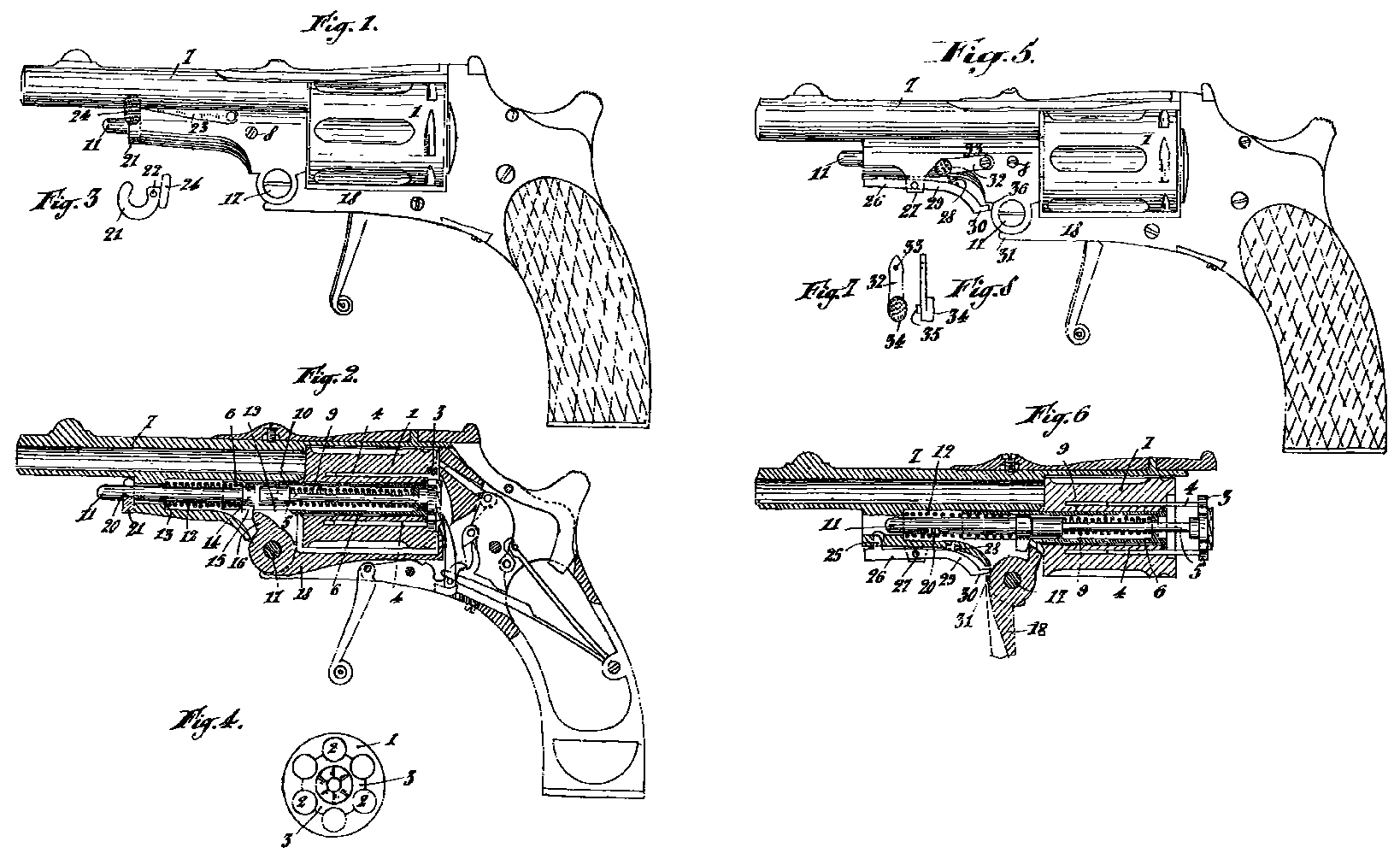
In the accompanying drawing—
Figure 1 is a side view of a revolver according to this invention,
Figure 2 is a vertical section of the same,
Figure 3 shows the U-shaped catch,
Figure 4 is a view of the rear face of the revolver drum,
Figure 5 is an elevation of a modified form of construction, and
Figure 6 is a section of the same showing the extractor withdrawn.
Figures 7 and 8 are views of the safety lever.
The revolver drum 1 has upon its rear face a circular recess which extends to about the centre of the cartridge chambers 2 and is adapted to receive a star shaped disc 3, so arranged as to complete the drum of usual construction. This disc 3 is guided by two small rods. 4 gliding in corresponding longitudinal perforations in the drum 1 and by a central rod 5 traversing a cylindrical casing 6 fixed to the barrel 7 by screws 8 and upon which the drum 1 can freely turn.
A spring 9 bearing at one end against the rear end of the casing 6 and at its other end against a head or collar 10 on the axial rod 5 has the tendency to maintain the star shaped disc 3 in its recess in the drum. The axial rod 5 can be so acted upon as to cause the disc 3 to move out of its recess on pressure being exerted by a rod 11, which under the influence of a spring 12 bearing at one end against an abutment 13 on the barrel and at the other end against a lug or enlargement 14 on the rod 11 and tending to press the rear end of said rod against the head 10 of the rod 5.
The rod 11 carries a finger 15 which under the action of the spring 12 is pressed against a cam 16 on the butt 18, the latter & the barrel being hinged together by a pin 17. An opening or slot 19 in the casing 6 allows of a free passage of the cam 16. In a groove or recess 20 in the outer end of the rod 11 engages a small U-shaped part 21, rotatable about a pivot 22 and maintained in place by a flat spring 23 bearing against an abutment 24 which is an integral part of the U-shaped device 21. When, after firing, a quick discharge of the empty cartridges is required, the butt 18 is caused to turn about its pivot 17 in order to free the rear face of the drum 1, after which the abutment 24 is pressed to disengage the rod 11. The latter by the influence of its spring 12 moves suddenly against the head 10 of the rod 5 and the star shaped disc 3 drives the cartridge cases out of the chambers 2 of the drum.
When it is desired to carefully extract the cartridges not fired, the abutment 24 is first operated so as to disengage the rod 11 and then the butt 18 is caused to turn about the pivot 17. In this manner the rod 11 advances progressively because the head 15 is retained by the cam 16; and this motion is transmitted to the rod 5 and to the disc 3 which extracts safely the cartridges not yet utilised.
The release of the rod 11 can be automatically effected by the mere rotation of the butt 18 about its pivot 17 (Figures .5 to 8). To this end the U-shaped part 21 is replaced by a hook or lug 25 on an arm 26 of a lever pivotted at 27, this lug entering a notch 20 in the rod 11 and being maintained therein by a small spring 28 bearing against the other arm 29 of the lever. This arm 29 terminates in a finger, 30 adapted to engage with a projection 31 on the butt 18, so as to withdraw the lug 25 from the notch 20. A small lever 32, Fig. 5, mounted to turn about a fixed pivot 33 (Figs. 7 and 8) carries at its end a projection or button 34 on the underside of which is arranged a stud 35 which engages in a recess 36 of the barrel support (Fig.5). In this position on turning the butt 18 about its pivot 17 the projection 31 will strike against the stud 35 and cannot operate the lever 26, 29, so that the drum 1 can be handled without fear of a sudden ejection of the disc 3.
In order to effect a rapid extraction of the cartridges after the stud 35 of the safety lever 32 has been withdrawn from the recess 36, it is sufficient to turn the butt 18 about the pivot 17, the projection 31 of which operates the lever 26,29 and causes the disengagement of the lug 25 from the notch 20. ‘
In order to withdraw the cartridges with precaution the lever 29 is operated by hand so as to release the rod 11, after which the butt 18 is caused to turn about its pivot 17 and the rod 11 advances progressively and correspondingly operates the rod 5 and the disc 3.
Having now particularly described and ascertained the nature of my said invention, and in what manner the same is to be performed, I declare that what I claim is:—
1. A cartridge ejective device for revolvers comprising a disc such as 3 held by a spring actuated rod in a recess in the rear of the revolving cartridge drum and extending partly over the cartridge chambers a second strong rod adapted to suddenly force the disc rod outward this second rod having a forward projection bearing against a cam on a pivotted butt, and a recess adapted to engage a retaining device operated by hand or automatically and a projection on the cam arranged to cooperate with a safety device to prevent when required the operation of the releasing lever, substantially as described.
2. A cartridge ejecting device for revolvers comprising a centrally perforated revoluble cartridge drum having a centrally recessed rear face, a disc fitting in said recess so shaped as to engage behind the rear rim of the inserted cartridges, a forwardly extending central spring actuated rod connected to the disc and normally retaining it in the recess, a second spring actuated rod in front of the first rod, means for normally holding the second rod with its spring compressed and mechanism for releasing said rod to thrust out the first rod, substantially as described.
3. In mechanism of the kind described a cam such as 16, substantially as and for the purpose described.
4. In mechanism of the kind described a spring rod locking device such as 26, 29, 30 and a safety lever arm such as 32 substantially as described.
5. The complete cartridge ejecting mechanism for revolvers substantially as described or illustrated in Figs. 1 to 4 or in Figs. 5 to 8 of the accompanying drawings.
Dated this 30th day of October, 1902
BOULT, WADE & KILBURN
Agents for the Applicant.