
British 7486
Specification of the Patent granted to Moses Poole, of the Patent Office, Lincoln’s Inn, in the County of Middlesex, Gentleman, for Improvements in Ordnance and Fire Arms.— Sealed January 19, 1837.
WITH AN ENGRAVING.
To all to whom these presents shall come, &c. &c.— Now know ye, that in compliance with the said proviso, I, the said Moses Poole, do hereby declare the nature of the invention, as communicated to me from abroad, and the manner in which the same is to be performed, are fully described and ascertained, in and by the following statement thereof, reference being had to the drawing annexed, and to the figures and letters marked thereon (that is to say):—
The invention consists of a means of constructing and applying a series of breeches to a single barrel of ordnance and of fire arms, as will be fully described hereafter.
Description of the Drawing.
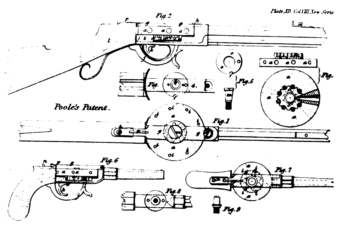
Fig. 1, represents a plan of part of a rifle, having the invention applied thereto.
Fig. 2, is a side view of fig. I.
Figs. 3, 4, and 5, are separate views of some of the parts.
No. XLVII. – Vol. VIII.
In each of these figures the same letters indicate similar parts. a, is a cylinder, in the periphery of which are formed a series of breeches, or holes, which, in using the piece of ordnance, or other fire arm, may successively be brought into a line with the barrel, and be retained securely there, till discharged ; each of the holes constituting a breech, it will be seen tends to the centre of the cylinder, a.
Fig. 6, is a side view of a pistol, having the improvements applied thereto.
Fig. 7, is a plan thereof, and
Figs. 8 and 9, are separate views of parts.
b, is an axis, on which the cylinder, a, turns, in order to bring a loaded breech to the barrel. c, is a plate, having a series of recesses, one to each nipple, or cone, on which the percussion cap is placed. This plate, c, is attached to the under part, or surface of cylinder, a, and revolves therewith, as will readily be understood, on an examination of the drawing ; hence the nipples are divided, one from the other, and the firing of one charge cannot communicate with another. e, is a steel plate, which is slightly dished, and made concave in the centre, and hence presses at the outer edges on, and covers, the recesses in the plate, c, thus more completely separating and excluding all fire from any one nipple to the other. f, is a recess, formed in the bearing plate of the cylinder, a, and also in the spring plate, e. The object of this recess is, that as a discharged breech comes round to that position, a detonating cap may be put on to the nipple. g, is a plate, which retains the axis of the cylinder, a, secure ; it is retained in its place by screws, at, h, h. And p, is a spring catch, which retains the cylinder, a, when a charged breech has been brought round to the barrel, charged breech has been brought round to the barrel, by a stud at one end entering one of the holes, i, i, as is clearly shewn in the drawing. j, is the hammer, which striking the detonating cap, fires the charge in the breech, which may be opposite the barrel. k, is the trigger, having a recess, or catch, into which the end of the hammer enters, when it is cocked. And 1, is the main spring. The end of the barrel is cut to the same curve as the cylinder, a, allowing for the cylinder, a, to move round with ease. m, is the screw, which retains the cylinder, a, in its place ; and it also forms the axis of the cylinder itself.
It will be seen, on looking at figs. 6 and 7, that the plate, g, moves on a hinge at one end, and is held down at the other, by a spring catch, n. The object of this arrangement is to give facility for removing a discharged cylinder, a, in order to replace it by one that is charged. This arrangement is particularly applicable to fire-arms. employed for military purposes, as the men could conveniently carry a number of cylinders, a, charged, and the simple act of placing a cylinder, a, would require much less time than loading one charge in the ordinary manner.
In making cannon it is prefered that the cylinder should turn on an horizontal axis in place of a vertical one ; in other respects the cylinder, a, will be similar to those above described, and the same may be discharged by a lock, or may receive a blow by hand with a suitable iron instrument. It will be seen that the charging of the breeches, in the cylinder, a, will be exceedingly easy, and will only require the charge to be forced a very short distance.
Having thus described the nature of my invention, I would remark, that I do not confine myself to the particular arrangement of lock for striking the percussion caps, as variations may be made ; nor do I confine myself to the use of percussion caps, as other means may be resorted to.
But what I claim is the mode of constructing the cylinder, a, combined with suitable means of discharging the charges successively from the series of breeches as above described.— In witness whereof, & c.
Enrolled July 19, 1837.