
Britain 4693
A.D. 1883, 2nd October, № 4693.
Breech Loading Fire-arms.
LETTERS PATENT to George Henry Needham of Wandsworth in the County of Surrey Gunmaker for an Invention of “Improvements in breech loading fire-arms”
PROVISIONAL SPECIFICATION left by the said George Henry Needham at the Office of the Commissioners of Patents on the 2nd October 1883.
George Henry Needha of Wandsworth in the County of Surrey, Gunmaker “Improvements in breech loading fire-arms”
The first part of my invention refers to the “grip” as applied to drop down fire-arms; I make the grip to extend from say the top to the bottom of the breech end of the barrels, although a shorter or longer distance may in some cases be desirable and with threads or teeth therein, the number of which may vary, In the breech block portion of the face of the action I form a slot to receive the lump of the grip and the threads or teeth and through the breech block or partially extending through same I form an aperture to receive a bolt or plug for locking and holding the grip by the threads or teeth. The bolt or plug is slotted to receive the grip and by turning the said bolt or plug the threads or teeth thereon are brought in and between the thread or teeth on the grip and the barrels are locked. By turning the plug in the contrary direction the slot in the plug is brought opposite the threads or teeth on the “grip” and the barrels are free to drop, The aperture to receive the plug may be tapped to take the plug which may have a thread corresponding therewith or in any other convenient way.
The next part of my invention refers to the cocking action. The chief object of this part of the invention is to cause the self cocking of the fire-arm and at the same time to produce a safety to prevent the striker falling until the safety is released, I cause one end of what I may call a safety lever (which latter is under control of the sportsman or other person using the piece) to act on one end of the main spring the lower arm of which is acted on by the arm on the tail end of the
striker or tumbler and so prevents the latter falling. The swivel on the striker is free to act on the other or upper arm of the spring when the safety lever is operated by the person using the gun, when this is done the lower or rear end of the spring is depressed and the other end raised when the tail end of the striker is free and the same is then free to fall as soon as, but not until the trigger is pulled. The act of releasing the safety lever allows the spring to return to its normal position and the striker or tumbler to full cock which in fact is the normal position of the tumbler but secured so that it cannot fall till the lever aforesaid is again operated on as before described.
The safety lever may be operated from the underside of the hand of the stock from the heel plate, butt end or from any other convenient position, When operated from the heel plate a rod passing up through the stock operates on a tail piece which latter acts on the main spring. The position of the action may be varied for example it may be at the front or rear of the striker and according to the position the various parts must be arranged in accordance therewith.
The extractors may be fitted to the side of the grip or lump action so that as the barrels are brought down the extractors are operated. The lever for this purpose is centered on the grip or lump one arm of which bears against the face of the action when opening the piece but of course any other suitable extractor may be used
I provide means to lock the tumbler and cocking action by means of a bolt operating on the plug and tumblers or strikers, This bolt is formed with indentations and projections thereon which are caused to act on a spring in the base of the lump slot or in the rear of the action; the plug is made with an aperture into which this spring is forced by turning the bolt, while at the same time the tumblers are prevented from falling. This bolt is operated by means of a key which can be removed when not required for use; by this means the action can be locked when the gun is not in use and no one can use it until the key is produced.
The safety lever before described is applicable for use as applied to revolving or repeating fire-arms as well as to break barrel guns, in which case the action described would be used to operate the rotation of the barrel and at the same time to act as a safety as before described. In some cases the long safety lever may be dispensed with and the action be produced from the trigger instead on the spring or springs in connection with the tumbler or tumblers or the seer may be made to act on the main spring
SPECIFICATION in pursuance of the conditions of the Letters Patent filed by the said George Henry Needham in the Patent Office on the 2nd April 1884.
George Henry Needham of Wandsworth in the County of Surrey, Gunmaker “Improvements in breech-loading fire arms”
The first part of my invention refers to the “grip” as applied to drop down firearms. I make the grip to extend from say the top to the Bottom of the breech end of the barrels although a shorter or longer distance may in some cases be desirable and with threads or teeth therein the number of which may vary. In the breech block portion of the face of the action I form a slot to receive the lump of the grip and the threads or teeth and through the breech block or partially extending through same I form an aperture t@ receive a bolt or plug for locking and holding the grip by the threads or teeth. The bolt or plug is slotted to receive the grip and by turning the said bolt or plug the threads or teeth thereon are brought in and between the threads or teeth on the grip and the barrels are locked. By turning the plug in the contrary direction the slot in the plug is brought opposite the threads or teeth on the “grip” and the barrels are free to drop. The aperture to receive the plug may be tapped to take the plug which may have a thread corresponding therewith or in any other convenient way.
The next part of my invention refers to the cocking action, The chief object of this part of the invention is to cause the self cocking of the firearm and at the same time to produce a safety to prevent the striker falling until the safety is released. I cause one end of what I may call a safety lever (which latter is under control of the sportsman or other person using the piece) to act on one end of the main spring the lower arm of which is acted on by the arm on the tail end of the striker or tumbler and so prevents the latter falling. The swivel on the striker is free to act on the other or upper arm of the spring when the safety lever is operated by the person using the gun when this is done the lower or rear end of the spring is depressed and the other end raised when the tail end of the striker is free and the same is then free to fail as soon as but not until the trigger is pulled. The act of releasing the safety lever allows the spring to return to its normal position and the striker or tumbler to full cock which in fact is the normal position of the tumbler, but secured so that it cannot fall till the lever aforesaid is again operated on as before described.
The safety lever may be operated from the underside of the hand of the stock, from the heel plate, butt end, or from any other convenient position. When operated from the heel plate, a rod passing up through the stock operates on a tail piece which latter acts on the main spring. The position of the action may be varied, for example it may be at the front or rear of the striker and according to the position the various parts must be arranged in accordance therewith.
The extractors may be fitted to the side of the grip or lump action so that as the barrels are brought down the extractors are operated. The lever for this purpose is centred on the grip or lump one arm of which bears against the face of the action when opening the piece but of course any other suitable extractor may be used.
I provide means to lock the tumbler and cocking action by means of a bolt operating on the plug and tumblers or strikers. This bolt is formed with indentations and projections thereon which are caused to act on a spring in the base of the lump slot or in the rear of the action; the plug is made with an aperture into which this spring is forced by turning the bolt, while at the same time the tumblers are prevented from falling.
This bolt is operated by means of a key which can be removed when not required for use, by this means the action can be locked when the gun is not in use and no one can use it until the key is produced.
The safety lever before described is applicable for use as applied to revolving or repeating firearms as well as to break barrel guns, in which case the action described would be used to operate the rotation of. the barrel and at the same time to act as a safety as before described. In some cases the long safety lever may be dispensed with and the action be produced from the trigger instead on the spring or springs in connection with the tumbler or tumblers or the sear may be made to act on the main spring.
In order that my Invention may be more fully understood I will now proceed to more fully describe-the same with reference to the accompanying drawings.
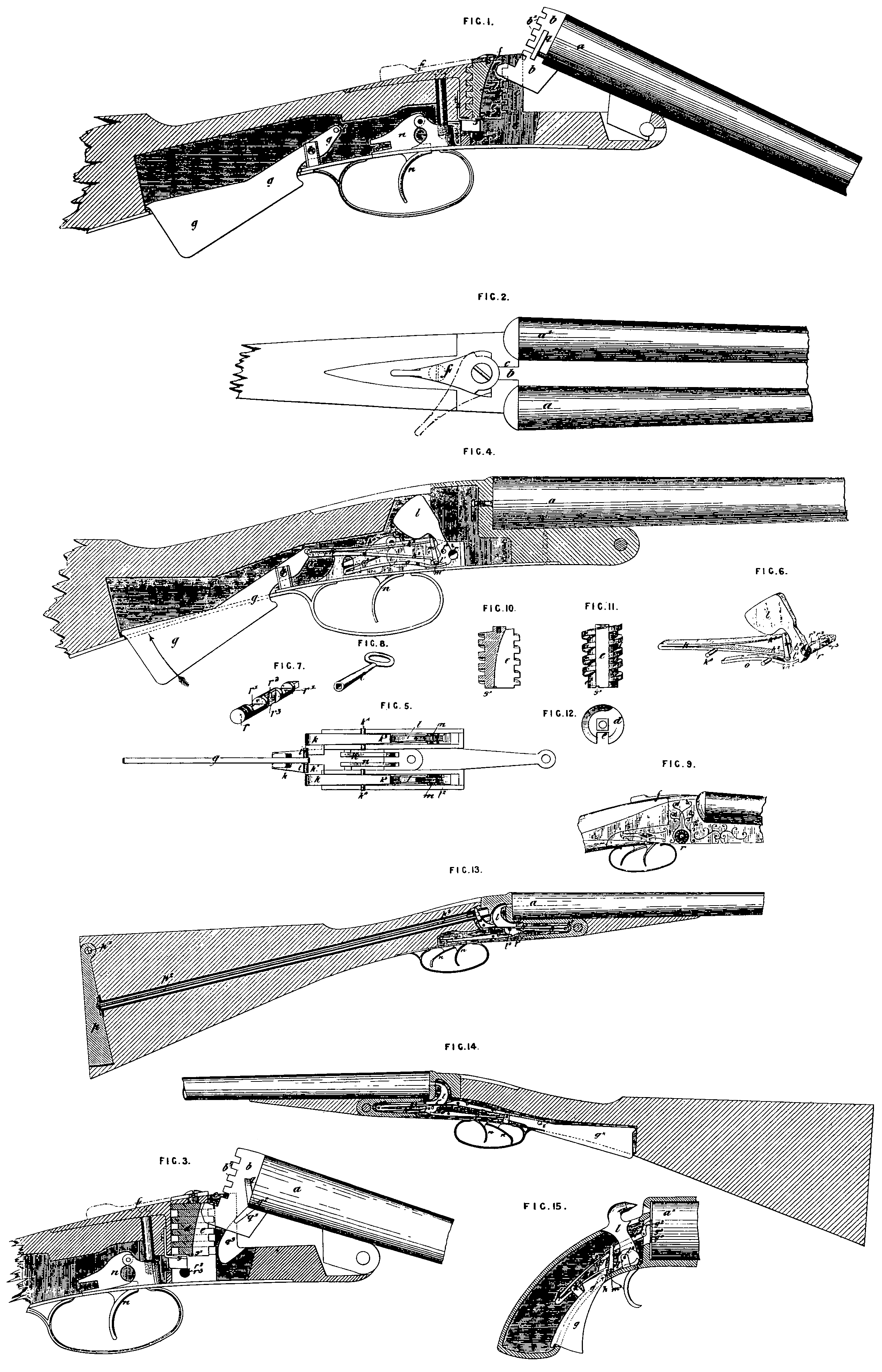
Figure 1 is a sectional elevation of so much of a firearm constructed according to my invention, showing the barrel open, as will be necessary to illustrate the grip action of the firearm; it will be noticed that most of the cocking action is removed. Figure 2 is a plan of same with the barrel closed. Figure 3 shows in art sectional elevation a somewhat modified form of grip action to that just illustrated. Figure 4 is a sectional elevation of a portion of a firearm showing my improved cocking action as applied thereto; Figure 5 is a plan view of a0 much of this action as will be necessary to explain same. Figure 6 shows the tumbler with the locking key applied thereto. Figures 7 and 8 are views of the locking pin and key for same detached. Figure 9 is an outside view of that part of the breech where the locking pin may be inserted. Figures 10, 11, and 12 are respectively section, elevation, and plan, of the plug. Figure 13 is a sectional elevation of a modified form of cocking action operated from the heel plate, and Figure 14 is another somewhat modified arrangement of cocking action from the arrangement shown at Figure 4. Figure 15 is a sectional side elevation of so much of a revolving firearm with my improvements applied thereto as will be necessary to explain this part of my invention. Similar letters of reference refer to like parts in all the figures.
a, a¹, show the barrels of the firearm, b is the grip or lump and b¹ the teeth thereon, c is the slot in the face of the action; d is the bolt or plug in same, detached views of which are shown at Figures 10, 11 and 12; a modified arrangement of this bolt being shown at Figure 3 where the bolt is made of a series of rings as shewn in the drawings; e shows the slot in the plug; f is the lever for operating the plug d. In Figure 1 the plug d is screwed into the action from above, and in Figure 3 it is inserted from the underside of the gun, g is the safety lever, pivotted at h and provided with pins or projections at i. k is the main spring on which the pins i act through a projection k¹ on same; k⁴ is the pin on which the main spring works. k³ is the lower arm of the main spring; l is the striker or tumbler pivotted at l²; l¹ the tail end of the striker or tumbler; m is the swivel or link pivoted at m¹ on to the arm l¹ of the striker or tumbler; k² is the upper arm of the mainspring which takes into the link m; n n are the triggers; o is the sear and o! the sear spring; at Figure 4 the sear and spring are shown made out of one piece of metal; at Figures 13 and 14 they are shown as being made of separate parts; o² is the tail piece which acts on the mainspring; p is the heel plate hinged at p¹; p² is the rod (which may be in a tube as shown and which tube may also serve as a breech pin to fix the action to the stock) passing from the heel plate up the stock to the tail piece o², Figure 13; where the action is shown in the front of the striker whereas at Figures 1, 4 and 5 this action is shown in the rear of the striker. In Figure 14 the mainspring is operated on by the tail piece o² which latter is operated by the lever g². In Figure 13 the main spring is shown as being operated by the tail piece o², rod p², and the heel plate p¹. In Figure 4 the mainspring is operated on by the safety lever g without the intervention, as is the case in Figures 13 and 14, of any intermediate parts; sometimes the mainspring may be caused to act on the tumbler without the link m, in which case the spring acts on m projection m on the tumbler shown at
Figures 13 and 14; a similar arrangement is applicable to a back action; q q are the extractors one only of which is shown in the drawing; q¹ Figure 3 is the lever for operating the extractor; q² is the lever centre on the lump b; q³ is the groove in the face of the action to receive the arm q! of the extractor as the barrels are closed; r is the locking bolt shown detached at Figure 7; r¹, r¹, are the indentations or recesses on bolt which allow for the fall of the tumbler; r², r³, are the indentations which act on the plug; s, Figures 1 and 3 is the spring in the base of the action; s¹ is the aperture in the plug d, into which the spring s takes or is forced by the turning of the bolt r; t Figure 8 is the key for burning this locking bolt Figure 7 which key fits on the square end of the locking b own at Figure 9, This bolt may be placed in any other suitable position in the action provided the key, which is in all cases detachable, can be easily inserted to operate the bolt.
At Figure 15 which shows a repeating firearm the parts are marked with corresponding letters, g shows the safety lever extending to the barrel cylinder a¹ or nearly so; h is the point at which the safety lever is pivoted; g¹ shows the continuation or prolongation of the safety lever; g² is the hook or pawl which operates on the ratchet of the cylinder; g³ is a spring for keeping the hook g³ against the face of the ratchet g⁴.
The action of the break barrel guns shown in the drawings is as follows :—
Supposing the firearm to be closed and locked and no cartridges in the barrels, then the key t is inserted into the aperture containing the bolt r into or onto the square or other shaped end of which the key is placed; on giving the key a half turn or thereabouts the bolt r is revolved, from the position shown at Figure 4 to that shown at Figures 1, 8 and 6, moving the half round of the bolt r clear of the tumbler l, and at the same time allowing the spring s to fall clear of the slot s¹ of the plug d, the gun is then unlocked and can be opened by the lever f, (which lever f may be closed automatically by a spring) being put into the position shown by the dotted lines Figure 2, this movement bringing the slot e in the plug d opposite the lump b thus withdrawing the teeth or threads of the plug d from the corresponding apertures of the grip b, the barrels then fall; the cartridges are inserted and the barrels closed, the locking being effected by the reverse action of the mechanism just described operated by the lever f which is then brought into the position shown by the full lines in Figure 2, The holding power thus obtained by the teeth of the plug d entering into the corresponding spaces on the lump b is very great and so long as the safety lever g remains in the position shown at Figure 4 the tumbler cannot fall even if the trigger n is pulled, but to enable this to be accomplished, or in other words, to enable the tumbler or striker to fall and explode the cartridge, press the safety lever upwards in the direction of the arrow, the safety lever turns on the pivot h and the pin i presses or acts on the projection k¹ of the mainspring, which latter being pivotted at k⁴, causes by its upper arm k³, an upward elastic pressure on the link m, which link being pivotted at m¹ to the tail end of the striker l, the latter is free to fall as soon as the trigger n is pulled, When the trigger is pulled, the safety lever still being kept pressed up if the direction of the arrow, the tumbler or striker l falls and explodes the cartridge, the mainspring k on the safety lever being released bringing the striker l back to its original position, owing to the arm k² of the mainspring pressing on the tail end l¹ of the striker l, and on releasing the safety lever g, the parts are again in their normal position, and the tumbler or striker cannot fall until the safety lever g is again raised; on opening the breech the cartridge cases are extracted by the extractor g Figure 3, or by any other approved extractor, another form of which is shown at Figure 1. When the gun is not required to be used the key t is used to turn the bolt r, whereby the half round portion of the bolt is brought into the corresponding recesses in the tumblers or strikers, and thus preventing them from falling, and the indentation r³ is brought under the spring s, thus forcing the latter into the slot s¹ in the plug d and the gun cannot possibly be opened or used without the key.
The action of the arrangements shown at Figures 18 and 14 is substantially the same as that described with reference to the previous Figures, only the operation as before stated on the mainspring by the safety lever is indirect instead of direct, and the action is obtained from the heel plate p in the one case, and the lever gˣ in the other.
The action of the revolver so far as the safety lever is concerned is similar to the action before described, except that the prolongation g¹ of the safety lever g, passes through a slot in the face of the action to operate the usual ratchet on the cylinder or barrels, so that the motion of the safety lever g in bringing upward pressure to bear on the link or part m causes the end g¹ to operate on the barrels or chamber a¹ The position of the ratchet may be changed by bringing it to the interior by prolonging the pivot of the barrels or cylinder, and fixing the ratchet on end of same. The shape of the various parts composing the firearm action must be necessarily varied to suit the class of arm to which it is to be applied.
Although I have described my invention as particularly applicable to break down firearms yet it is to be understood that the several parts of the invention are applicable to other firearms which are not break barrel firearms.
Having now described the nature of my said invention and in what manner the same is to be performed I declare that I claim as my aforesaid “Improvements in breechloading firearms,”
First In drop down firearms the construction of the grip with teeth, in combination with a slotted plug or bolt, having teeth thereon, which lock and unlock with the teeth on the grip, all operating and arranged in manner substantially as hereinbefore described and illustrated in the accompanying drawings.
Second:— The self-cocking action, in and by the employment of the safety lever g, acting directly, or indirectly on the mainspring of the action, and operated by the hand or shoulder of the operator, all substantially as hereinbefore described and illustrated with reference to the accompanying drawings, together with my mere modification thereof.
Third:— The cartridge extractor, constructed as described, in combination with the grip locking action, substantially as hereinbefore described and illustrated with reference to Figure 3 of the accompanying drawings.
Fourth:— The employment of a locking bolt, operated by a detachable key, for locking the grip or tumblers (or strikers) or both, when the firearm is not required for use substantially as hereinbefore described and illustrated with reference to the accompanying drawings.
Fifth:— The application to, and the combination with, repeating firearms of the safety lever g, constructed arranged and operating substantially as hereinbefore described and illustrated with reference to Figure 15 of the accompanying drawings.
Sixth:— The general arrangement and combination of parts of firearms substantially as, and for the purposes hereinbefore described and illustrated with reference to the accompanying drawings
In witness whereof I the said George Henry Needham have hereunto set my hand and seal this First day of April in the year of our Lord One thousand eight hundred and eighty four.
GEORGE HENRY NEEDHAM (L.S)