
Britain 3258
A.D. 1865, 16th December. N° 3258.
Breech-loading Fire-arms, &c.
LETTERS PATENT to Alfred Vincent Newton, of the Office for Patents, 66, Chancery Lane, in the County of Middlesex, Mechanical Draughts-man, for the Invention of “Improvements In Breech-Loading Fire-Arms And Rotating Breech Cylinder Pistols, And Cartridges To Be Used Therewith.”— A communication from abroad by Silas Crispin, of the City of New York, in the United States of America.
Sealed the 6th March 1866, and dated the 16th December 1865.
PROVISIONAL SPECIFICATION left by the said Alfred Vincent New ton at the Office of the Commissioners of Patents, with his Petition, on the 16th December 1865.
ALFRED VINCENT NEWTON, of the Office for Patents, 66, Chancery Lane, in the County of Middlesex, Mechanical Draughtsman, do hereby declare the nature of the said Invention for “Improvements In Breech-Loading Fire-Ass And Rotating Breech Cylinder Pistols, And Cartridges To Be Used Therewith,” to be as follows:—
This Invention relates to certain improvements in breech-loading guns and pistols which will admit of the use of a peculiar construction of cartridge, also constituting part of the present Invention, and calculated to form a perfect gas check for those arms. The barrel of the gun is hinged to the breech or stock at the under side to provide for the insertion of the charge at the rear and of the barrel, and a spring strap attached to the upper side of the barrel and catching on to a hub on the breech is used to make good the connection between the breech and barrel. The cartridge employed has a metal case with a flange or annular projection some distance in advance of the rear end of the case. This annular projection fits into an annular recess made to receive it, one half being in the barrel and the other half in the breech. When, therefore, the cartridge is ignited this metal flange or projection will effectually close the opening between the breech and barrel, and prevent the discharge of lateral fire.
To adapt this improvement to repeating arms constructed on the rotating breech principle the breech is divided into two parts at right angles to its axis, the larger portion being mounted on a pin carried by the barrel, and the latter on a pin projecting from the recoil shield or breech piece. These two parts are intended to rotate together under the action of the ordinary driver, and they are temporarily connected together by the insertion of the metallic cartridges in the chambers of the rooting breech, or it may be by dowel pins. To allow of the insertion of the cartridges the sections of the breech are made to separate readily, the barrel and stock being connected together by a binge as in the gun, and further secured by an elastic strap. The rim or annular projection on the cartridges lies in a recess made to receive it in the line of section of the rotating breech, and slots are made in the periphery of the rear section to allow the hammer to reach and strike upon the rim; or in lieu of these slots an igniting rod within the upper part of the recoil shield may be used to receive the blow of the hammer and impart the same to the explosive matter in the cartridge. This means of filing the charge is also adapted to the above-described breech-loading gun.
The improved cartridge is a primed metallic cartridge, which serves not only as a gas check but offers facilities for removal (when discharged) by applying the fingers to the rear end thereof. The cartridge may have a seamless metallic case made in the ordinary manner, or a case made of thin wrapped sheet metal. In it there is formed to receive the priming or percussion powder a rim or annular recess anywhere intermediate between the bottom of the ease and that end of it into which the bullet is inserted. A paper or a metallic cup, or a cup of elastic substance may be inserted in the cartridge case before the same is filled. The case is then charged with powder and boll as is done in making ordinary primed metallic cartridges. The annular recess or rim is formed in the ease by the insertion therein of a properly shaped tool mobile the case is being rotated in a lathe. It will be understood that when the improved cartridge is fired the case will form a perfect gas check, and on the breech being opened the empty case can be removed by the fingers without the employment of any auxiliary mechanical device.
SPECIFICATION in pursuance of the conditions of the Letters Patent, Mel by the said Alfred Vincent Newton in the Great Seal Patent Office on the 16th June 1866.
TO ALL TO WHOM THESE PRESENTS SHALL COME, I, ALFRED VINCENT NEWTON, of the Office for Patents, 66, Chancery Lane, in the County of Middlesex, Mechanical Draughtsman, send greeting. WHEREAS Her most Excellent Majesty Queen Victoria, by Her Letters Patent, bearing date the Sixteenth day of December, in the year of our Lord One thousand eight hundred and sixty-five, in the twenty-ninth year of Her reign, did, fur Herself, Her heirs and successors, give and grant unto me, the said Alfred Vincent Newton, Her special licence; that I, the said Alfred Vincent Newton, my executors, administrators, and assigns, or such others as I, the said Alfred Vincent Newton, my executors, administrators, and assigns, should at any time agree with, and no others, from time to time and at all times thereafter during the term therein expressed, should and lawfully might make, use, exercise, and vend, within the United Kingdom of Great Britain and Ireland, the Channel Islands, and Isle of Man, an Invention for “Improvements In Breech-Loading Fire-Arms And Rotating Breech Cylinder Pistols, And Cartridges To Be Used Therewith,” being a communication front abroad, upon the condition (amongst others) that I, the said Alfred Vincent Newton, my executors or administrators, by an instrument in writing under my, or their, or one of their hands and seals, should particularly describe and ascertain the nature of the said Invention, and in what manner the same was to be performed, and cause the same to be filed in the Great Seal Patent Office within six calendar months next and immediately after the date of the said Letters Patent.
NOW KNOW YE, that I, the said Alfred Vincent Newton, do hereby declare the nature of the said Invention, and in what manner the same is to ho performed, to be particularly described and ascertained in and by the following statement, reference being had to the Drawing hereunto annexed, and to the letters and figures marked thereon (that is to say):—
This Invention, as communicated to me by my foreign correspondent, relates to certain improvements in breech-loading guns and pistols which will admit of the use of a peculiar construction of cartridge, also constituting part of the Invention, and which cartridge is intended to form a perfect gas check for those arms.
The first improvement has reference to that kind of breech-loading gun in which the chamber for receiving the cartridge is transversely divided, one portion of such chamber being formed in the breech piece attached to the stock or neck of the stock, and the other portion being formed in the breech end of the barrel; the two parts are connected by a hinge joint, which will allow of the opening of the breech for the insertion of the cartridge and the withdrawal of the case. This part of the Invention consists in so forming the two parts of the cartridge chamber with a chamfer on the mouth of each that when they are brought together to hold the cartridge there shall be an annular groove adapted to accommodate an annular rim or fulminate flanch on the body of a peculiar construction of cartridge herein-after to be more fully described.
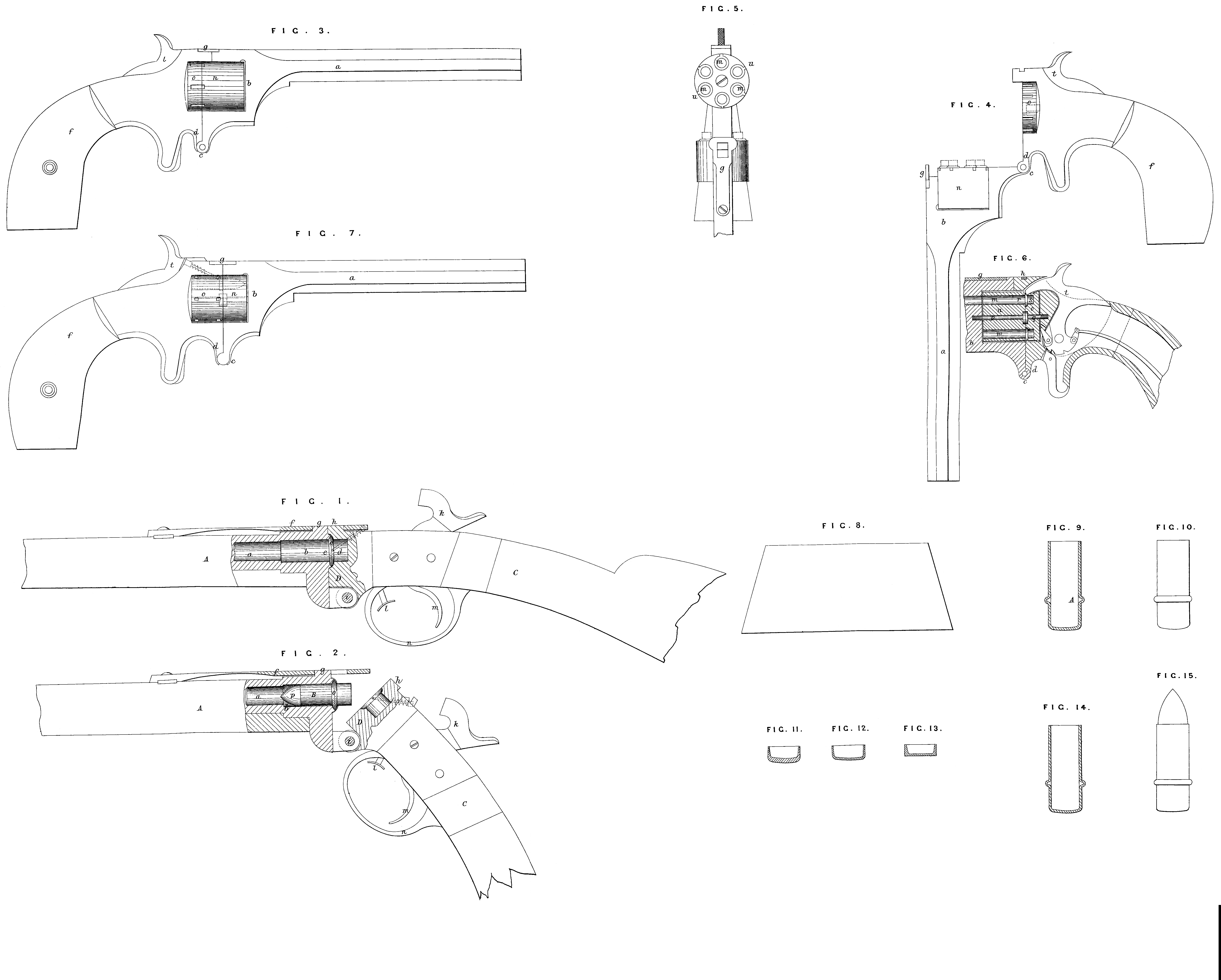
In the accompanying Drawing, Fig. 1 is a sectional elevation of a breech-loading carbine constructed according to the first head of the Invention, and Fig. 2 is a similar view of the same, showing the breech open for the insertion of the cartridge.
In these views A, A, are the barrel stock and barrel, and C the stock; D is a breech piece, which is formed on or attached permanently to the stock C, and in which is formed a portion of the cartridge chamber b. The other portion of the chamber b is formed in the rear end of the barrel a. and the two parts are hinged together at i in such manner that they can be swung apart as shewn at Fig. 2, and closed up as shown at Fig. 1. On the upper side of the breech piece D is a projection or lug Ti, and on the top of the breech of the barrel a is another and similar lug g. Over these two lugs shuts a spring bar f, which serves to hold the parts together, as shewn at Fig. 1; / is a sliding rod or bar which serves to force up the rear end of the spring f to unlock the parts so that they can be swung open, as shown at Fig. 2, for the insertion of the cartridge previous to firing, and for the extraction of the discharged or empty cartridge case. B represents one of the new metallic cartridges fitted with a conical ball p and inserted into the breech of the barrel a (or the forward portion of cartridge chamber b); n is the trigger guard; m, the trigger; and k, the cock or hammer, all of which parts may be constructed and arranged in any desired manner. The hammer acts upon a pin or rod which slides in the site of the breech D, and is so arranged as to impart the blow from the hammer to the annular Ranch or fulminate rim o of the cartridge B. By reaming out the edges of the two portions of the chamber b, as shewn at c and d, Fig. 1, an annular channel or groove is formed for the reception of the rim o of the cartridge.
Breech-loading guns constructed as described to receive the new cartridge having the fulminate rim between the base and forward end of its case may be used with great advantage. It will be seen that by simply pressing up the rod 1 with the forefinger the spring f will be forced up and the parts allowed to assume the position of Fig. 2 for the ready and easy insertion of the cartridge or extraction of the empty case; in the latter instance, from a large portion of the empty case protruding from the chamber 6, the case can be readily withdrawn by the fingers.
Under this head of the Invention I claim constructing breech-loading guns with the cartridge chambers formed in two parts, as described, to receive the fulminate flanch of the cartridge, substantially in the manner and for the purpose above set forth.
The second part of the Invention consists in adapting breech cylinder fire-arms to receive the improved flanged metallic cartridge and facilitate the removal of the waste cases therefrom.
Fig. 3 is a side view of a pistol having a revolving many-chambered breech piece or cylinder, the breech cylinder being constructed in two parts; Fig. 4 is a side view of the pistol, showing the breech open; Fig. 5 is a partial plan or top view of the pistol when in the position represented in Fig. 4; Fig. G is a partial, central, longitudinal, vertical section; and Fig. 7, a side view of the pistol with the breech divided into two parts or sections at or near its point end. a, a, on the Drawing represent the barrel of the pistol attached to or formed with its frame b hung by a hinge joint c to and upon the lower side d of the stock f, which frame and stock are held together at their upper parts when closed by the interlocking of a spring plate g (on the barrel frame) with the projecting piece h on the stock. The breech cylinder is formed in two parts or sections n, o, with the division near the closed or rear end thereof, and it has a series of chambers in, 2n, in, extending nearly through its length, and of the same size as the bore of the barrel a. One of these sections, n, turns upon a shaft p of the barrel frame, and the other upon a shaft q of the stock. The two sections aro so arranged that when brought together by the closing of the barrel frame and stock as before described the contiguous ends of each section will perfectly coincide with each other, as also will their chambers, which are brought in turn in line with the bore of the barrel by the devices ordinarily employed for revolving the breech cylinder. In the chambers in, formed in the two sections or parts of the breech cylinder, the metallic cartridges, represented by red lines in Figures 4 and 5, and hereafter to be fully described, are inserted, they extending across from one section to the other, with their fulminating rims held by and in the shoulders r and s of the contiguous ends of the sections; these cartridges, when brought in turn to and in a line with the barrel by and through the ordinary devices usually employed for revolving the breech cylinder, are discharged by means of the hammer t, which is made of the proper shape and size to strike their fulminating rims, the periphery of the rear section o being cut away at the proper point, as seen at u, u, in order to expose the rims to the action of the hammer. From the above it is evident that as the metallic cartridges extend from one section to the other of the breech the two parts must necessarily revolve together and as one piece when the rear portion o is actuated as above described, but in lieu thereof the sections may be secured together by dowel pins either inserted in one or the other if desired or deemed expedient, and furthermore it is apparent that in order to insert the cartridges within the breech cylinder its two parts must be opened from each other, as represented ready for use. To remove the waste cartridge cases the two parts of the cylinder are re-opened as before described for charging the chambers, when by taking hold of the projecting portions they can be easily and readily removed. Among the many advantages resulting from the above-described arrangement or construction of the breech cylinder of the pistol, in addition to the facility with which the waste cartridge cases can be removed therefrom, may be here mentioned that the rear end of the cylinder can be entirely closed, thus protecting the cartridges from contact with the stock with which they have heretofore generally come in contact, and the objections to which are well known to all conversant with fire-arms, and furthermore by being thus entirely closed within the cylinder they are not liable to injury from any cause whatsoever.
In Fig. 7 a modification of the above-described improvement is represented. It consists in dividing the breech cylinder at or near its front end, which necessitates a corresponding change in the position of its fulminating rim of the metallic cartridge and the use of an igniting rod within the upper portion of the stock. This rod is arranged in such a manlier that the striking force of the hammer of the pistol shall communicate through the same with the fulminating rim of the cartridges, as is plainly represented in Fig. 7. I would hero remark that although I have described the second part of the Invention in connection with a pistol having a revolving chambered breech cylinder, it is manifest that it can be as well applied to other and various forms of rotating breech pieces, and therefor I do not intend to limit myself to its use for any one particular form of cylinder breech pieces.
Under the second head of the Invention I claim the application to a revolver of a transversely divided cylinder constructed and operating in the manner and for the purpose above described.
I will now proceed to describe the improved cartridge which forms the third and last part of this Invention.
Fig. 8 is a piece of sheet metal cut to the shape required to form into a cartridge case by wrapping; Fig. 9 is a longitudinal section of such a case in one stage of its manufacture; Fig. 10 is a side view of the finished case; Figures 11, 12, and 13 are cups or discs for insertion in the cases before filling, the first being of paper, the second of metal, and the last of an elastic material; Fig. 14 is a longitudinal section of a seamless case; and Fig. 15, an elevation of the finished cartridge. ‘rho object of this part of the Invention is to provide a primed metallic cartridge extremely simple and cheap in its construction, and which will form a perfect gas check in breech-loading fire-arms, and can after the discharge of the piece be removed by the fingers with great ease without the use of any special means. The cartridge may have a seamless metallic case made in the ordinary manner or a case made of thin wrapped sheet metal. In the case a rim or annular recess is formed to receive the priming or percussion powder at any part of its length between the bottom of the case and that end of it into which the bullet is inserted. To make the cases by wrapping there are cut from sheet copper or other suitable thin sheet metal of about fifteen-thousandths of an inch in thickness pieces of the form shown at Fig. 8. These pieces are in length about five or more diameters of the bore of the gun in which the cartridge is to be used, and two-thirds or more diameters of the said bore more in width than the cartridge is intended to be in length. A cylindrical former of either wood or iron, the latter is preferred, is now placed on one of the pieces and pressed and rolled until the piece is wrapped closely and completely around it, the lower or open end of the wrapped metal projecting about two-thirds of a diameter of the former beyond the end of the former. This end of the former in shape is made to match the base of the chamber of the arm for which the cartridge is intended, whilst the gauge of the former must be such that the cartridges when finished shall fit the chamber of the gun neatly. The wrapped metal is now crimped over the end of the former with the fingers or with a crimping tool. After thus compressing the metal tightly around the end of the former the metal cylinder still on the former is placed in an iron, steel, or wooden die, and the former is struck a smart blow or pressed on its uncovered end, and the base of the cylinder receives the form of the die. The cylinder thus formed is placed in a suitable die in a lathe, and a proper tool being applied to the inner surface of the cylinder at the desired point the cylinder is rotated until the thin metal is spun out to the required diameter, and the rim or annular recess A, Fig. 9, for containing the percussion powder, is formed. The cylinder so prepared is now placed in a swedge properly fitting it, and is by pressure or by smart blow pressed into the finished state shewn in Fig. 10. Fulminating or percussion powder is now inserted in the rim in the ordinary manner. A paper cup like that shewn in Fig. 11, or a metallic cup like that shewn at Fig. 12, or a cup of elastic substance like that shewn at Fig. 13, and made in any approved manner, may be inserted in the cartridge case before the same is filled. The case is then charged with powder and ball as is done in making ordinary primed metallic cartridges. If it is desired to use seamless cases they are prepared in the ordinary manner and then placed in the lathe, and the annular recess or rim is formed in them in the manner above described. When the cartridge made as above described is fired the case will form a perfect gas check, and on the breech being opened the empty case can be removed by the fingers without the employment of any auxiliary mechanical device. It is manifest that cartridges so made can be placed in the arm in which they are to be used as rapidly as any other primed cartridge, also that the case of no metallic cartridge can be so simply, rapidly, and certainly removed from the breech loader; it is also manifest that these cartridges can be used in breech-loading shot guns.
Under this head of the Invention I claim constructing cartridges as described, with the fulminate placed within a projecting annular recess or rim formed at a point between the ends of the cartridge case, for the purpose above set forth.
In witness whereof, I, the said Alfred Vincent Newton, have hereunto set my hand and seal, the Sixteenth day of Juno in the year of our Lord One thousand eight hundred and sixty-six.
A. V. NEWTON. (L.S.)
Witness,
J. W. Monsn,
66, Chancery Lane.