
US 135377
UNITED STATES PATENT OFFICE.
OTIs A. SMITH, OF MIDDLEFIELD, CONNECTICUT.
IMPROVEMENT IN REVOLVING FIRE-ARMS.
Specification forming part of Letters Patent No. 135,877, dated January 28, 1873.
Case A.
To all whom it may concern:
Be it known that I, Otis A. Smith, of Middlefield, in the county of Middlesex and State of Connecticut, have invented a new Improvement in Revolving Fire-Arms; and I do here by declare the following, when taken in connection with the accompanying drawing and the letters of reference marked thereon, to be a full, clear, and exact description of the same, and which said drawing constitutes part of this specification, and represents, in—
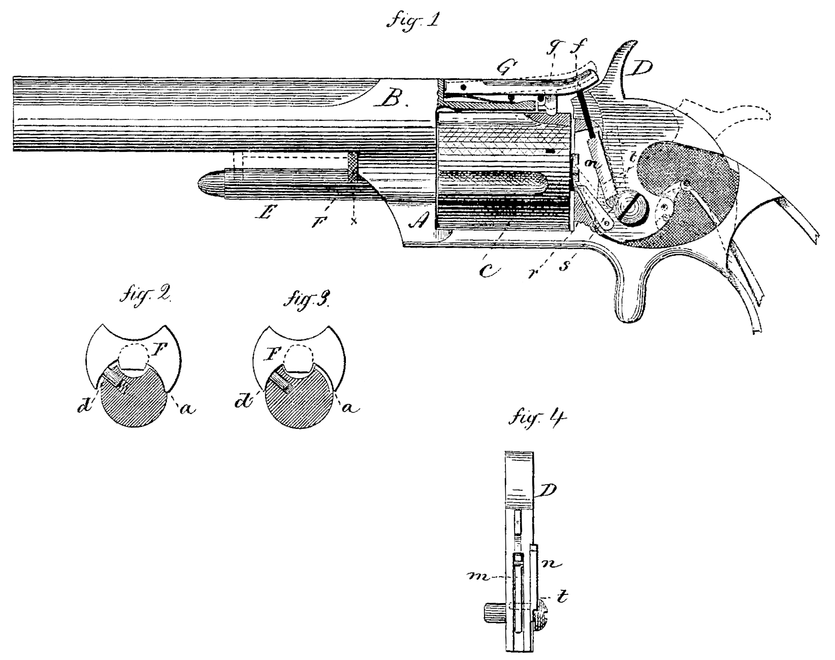
Figure 1, a side view, a portion of the frame removed to show the mechanism; Figs. 2 and 3, transverse sections on the line x, enlarged; Fig. 4, a front view of the hammer, detached.
This invention relates to an improvement in what are known as revolving fire-arms; and it consists, first, in the manner of operating and securing the center-pin upon which the cylinder revolves; second, in the arrangement of a latch or lever upon the hammer, which acts, as the hammer is drawn back, to raise the stop before the pawl engages the ratchet of the cylinder, and to release the stop before the hammer is set at full-cock.
A is the frame, of common construction, carrying the barrel B, the revolving cylinder C, hammer D, and arm E, beneath the barrel, in substantially the usual manner. Between the barrel and arm E a finger-piece, F, is arranged, and from this the center-pin extends through the frame and cylinder to form the axis, upon which the cylinder turns. This center-pin is drawn from the cylinder or moved into place by taking hold of the finger-piece F, being represented as drawn out in broken lines, Fig. 1, for the release of the cylinder. In order to secure the center-pin when set into position to hold the cylinder I form a notch, a, on one side of the arm E and upon the opposite side a spring-stud, d, as seen in Figs. 2 and 3. When the finger-piece F is moved into the position seen in Fig. 1— that is, to its place of rest— the spring-stud forces out one side of the finger-piece, as denoted in Fig. 2, causing the opposite side to drop into the notch a, as seen in the same figure, thus holding the center-pin in that position. To drawback the center-pin with the thumb and finger upon opposite sides of the finger-piece F, turn the finger-piece into the position seen in Fig. 3, which forces the stud d into the arm and the opposite side from the notch a, leaving the finger-piece free to be withdrawn. The finger-piece is guided in its movement by a recess in the upper side of the arm E. The spring-stud d, while best arranged in the arm, as shown, may, if desirable, be inserted in the finger-piece with the same result. G is a stop arranged upon the upper side of the frame, and with a stud, g, upon its under side to drop into a notch at the setting of each chamber into proper position for firing, and in order to make this a dead-lock it is necessary that the stop should be raised when it is desired to present a new chamber or rotate the cylinder. To do this I place a slide, f, denoted in solid black, Fig. 1, through the frame and arrange upon the side of the hammer D a latch, n, which, when the hammer is down, will fall beneath the pin f, the other end of the latch being pivoted to the hammer eccentric ally to its pivot, and with a spring, m, (see Fig. 4) the tendency of which is to force the latch forward beneath the slide f. A shoulder, t, is formed on the latch, and a corresponding shoulder, 8, on the hammer relatively to each other, so that as the hammer is thrown back the latch will rise with the hammer until the stop is raised sufficiently high to release the cylinder; then the pawl r engages the cylinder and commences its rotation. At this point the shoulder t of the latch and shoulder s of the hammer come together and the latch is drawn back from beneath the slide f, moving with the hammer, as denoted in broken line. When the hammer is again thrown forward the latch falls beneath the slide and operates as before.
I claim as my invention—
1. In a revolving fire-arm, the center-pin, provided with the finger-piece F working between the arm E and the barrel, the said arm E formed with a notch, a, and having a spring stud, d, to force and hold the said finger-piece into the said notch, substantially as described.
2. In combination with the cylinder C, stop G, and hammer D of a revolving fire-arm, the latch in and the slide f, constructed and arranged to operate substantially as set forth.
OTIS A. SMITH.
Witnesses:
C. D. FITCH,
M. D. ANDRUS.