
US 670862
UNITED STATES PATENT OFFICE.
OSCAR F. MOSSBERG, OF FITCHBURG, MASSACHUSETTS.
CYLINDER-LATCH FOR REVOLVERS.
SPECIFICATION forming part of Letters Patent No. 670,862, dated March 26, 1901.
Application Filed August 30, 1899. Serial No. 728,938. (No model.)
To all whom it may concern:
Be it known that I, OSCAR F. MOSSBERG, a citizen of the United States, residing at Fitchburg, in the county of Worcester and Commonwealth of Massachusetts, have invented a new and useful Improvement in Cylinder-Latches for Revolving Firearms, of which the following is a specification, accompanied by drawings forming a part of the same, in which—
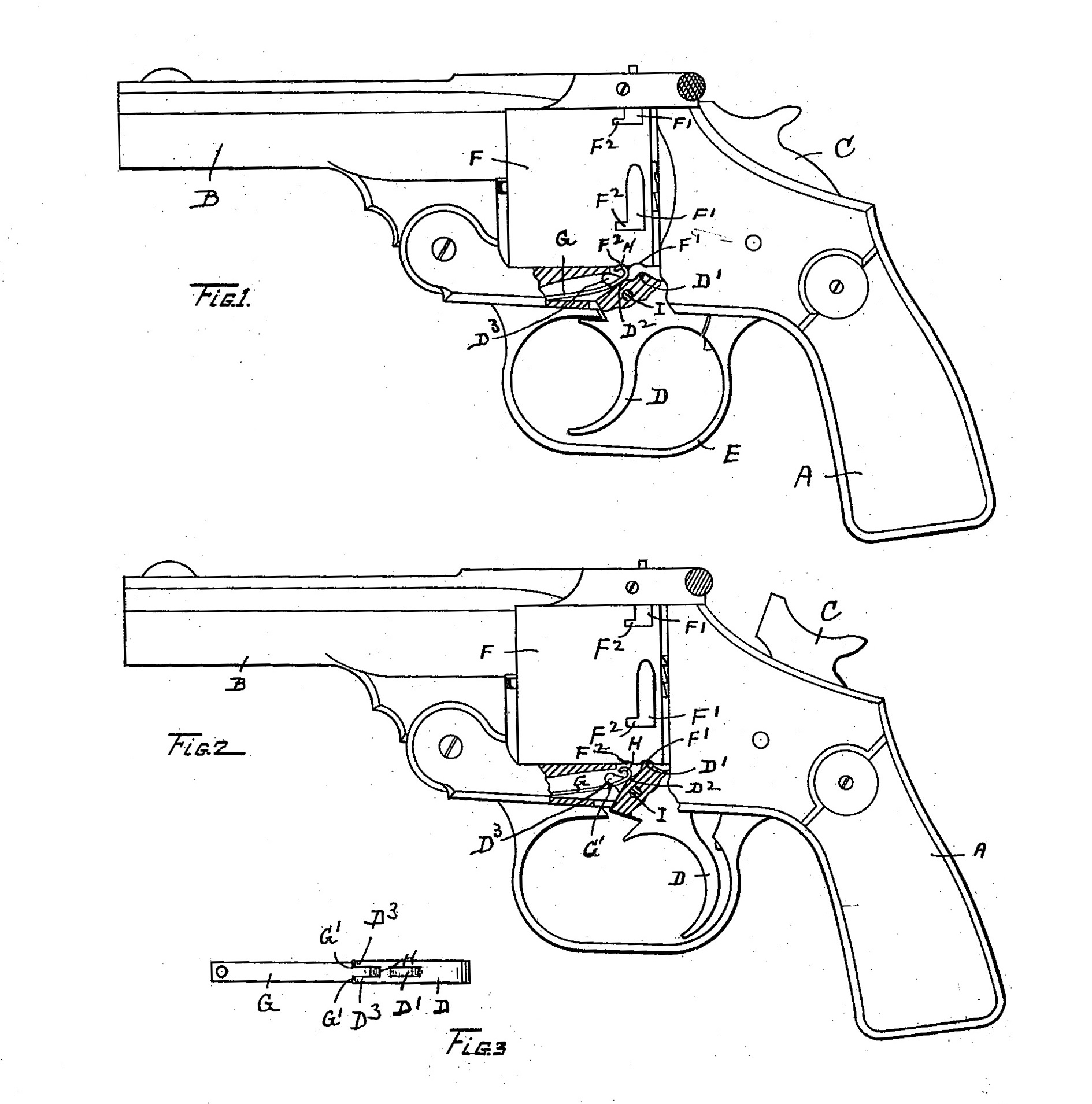
Figure 1 represents a side view of a revolving firearm with a portion shown in sectional view in order to disclose that part of the operative mechanism which embodies my invention. Fig. 2 represents the same view as that shown in Fig. l, except that the operative parts disclosed by the sectional view are shown in the position assumed when the hammer is cocked. Fig. 3 represents a top and detached view of the spring G and trigger D.
Similar letters refer to similar parts in the different figures.
In the drawings, A denotes the handle or stock, B the barrel, C the hammer, D the trigger, and E the trigger-guard, of a revolving firearm such as are now in common use.
F represents the revolving cylinder provided with notches F’ F’ and F2 F2 to receive latching mechanism, by which the cylinder is held from rotating. The notches F2 are adapted to receive the curved end H of a spring G, which is attached at one end to the frame of the firearm and bears against the point D2 of the trigger. The spring G is provided with shoulders G’ G’ in contact with the projecting lugs D3 on the trigger D.
When the hammer C and trigger D are in their normal position, as shown in Fig. l, with the spring G bearing against the point D2 of the trigger the curved end H is arranged to engage one of the notches F2, thereby holding the cylinder F from rotation; but when the hammer C is cocked and the trigger drawn back into the position shown in Fig. 2 the projecting lugs D3 press against the shoulders G’ of the spring G, thereby depressing the spring and withdrawing the curved end H out of engagement With the cylinder and at the same time the rocking motion of the trigger carries its lug D’ into engagement with one of the notches F. The rotating cylinder F is therefore locked in position by the end H of the spring G when the hammer and trigger are in their normal position, as in Fig. 1; but when the hammer is cocked and the trigger rotated on its pivot-pin I from the position shown in Fig. 1 to that shown in Fig. 2 the curved end H of the spring G is withdrawn from the cylinder, and the continued rocking of the trigger D carries the projecting lug D’ into engagement with the cylinder. The rotation of the cylinder is effected in the usual and well known manner in arms of this class during the period between the engagement of the spring G and the engagement of the lug D’ with the cylinder.
The free end of the spring G is reduced in width to form the shoulders G’, and the reduced end of the spring is inclosed between the lugs D3 of the trigger, which serve to hold the spring from lateral displacement and maintain the curved end H in the plane of the notches F2 as the cylinder is rocked and brought into position for tiring. The locking mechanism by Which the hammer is cocked, held in its cocked position for tiring, and released by the action of the trigger may be of any known form of construction and forms no part of my present invention, which relates solely to the cylinder-latching mechanism, whereby the cylinder is alternately locked at each end of the rocking movement of the trigger.
I do not claim, broadly, a spring-latch arranged to engage the cylinder and be depressed by the rocking movement of the trigger. By my construction I am able to attach the spring G to the frame by a single screw or rivet, and I bring the free end of the spring into accurate registration with the notches in the cylinder by means of the lugs D3 D3 on the trigger, and thereby hold the cylinder in accurate tiring position, and I utilize the lugs to depress the spring G, by means of the shoulders G’ G’, in the path of the lugs D3 D3 as the trigger is rocked, thereby simplifying the construction of the latching mechanism.
What I claim as my invention, and desire to secure by Letters Patent, is—
1. The combination with a rotating notched cylinder of a spring G attached at one end to the frame of the rearm and having its free end curved to form a latch adapted to engage the cylinder-notches, shoulders G’, G’ near the curved end of said spring, a pivoted trigger D bearing against said spring to raise it into engagement with the cylinder, lugs D3, D3 projecting from said trigger on opposite sides of said springs and engaging the shoulders G’, G’ in order to depress said spring as the trigger is rocked and hold it from lateral displacement, substantially as described.
2. The combination with a rotating notched cylinder of a spring G attached at one end to the frame of the firearm and having its free end curved to form a latch adapted to engage the cylinder-notches, shoulders G’, G’ near the curved end of said spring, a pivoted trigger D bearing against said spring to raise it into engagement with the cylinder, lugs D, D’ projecting from said trigger on opposite sides of said springs and engaging the shoulders G’, G’ in order to depress said spring as the trigger is rocked and hold it from lateral displacement, and a projection on said trigger adapted to engage the cylinder as the trigger is rocked to depress said spring, substantially as described.
Dated this 24th day of August, 1899.
OSCAR F. MOSSBERG.
Witnesses:
GUSTAF ELLSTROM,
ALBERT E. ADDIS.