
US 611977
UNITED STATES PATENT OFFICE.
ORLANDO ROSE, OF CROWN POINT, INDIANA.
SAFETY ATTACHMENT FOR FIREARM-LOCKS.
SPECIFICATION forming part of Letters Patent No. 611,977, dated October 4, 1898. Application filed May 5, 1897, Serial No. 635,194, (No model.)
To all whom it may concern:
Be it known that I, Orlando Rose, of Crown Point, in the county of Lake and State of Indiana, have invented certain new and useful Improvements in Safety Attachments for Guns and Revolvers; and I do hereby declare the following to be a full, clear, and exact description of the invention, such as will enable others skilled in the art to which it appertains to make and use the same.
The object of this invention is to provide an attachment for guns or revolvers that will positively prevent the hammer being moved to explode the cartridge before it is first brought to a full-cock, the movement of the hammer to the full-cock bringing a trip-lever under the locking or safety lever to hold it out of the path of the hammer, the said ham mer operating the trip-lever to free the safety lever.
In the following specification I have entered into a detailed description of the invention, reference being had to the accompanying drawings and to numerals thereon, which designate the different parts, and what I consider to be the novel features of construction are specifically recited in the claims.
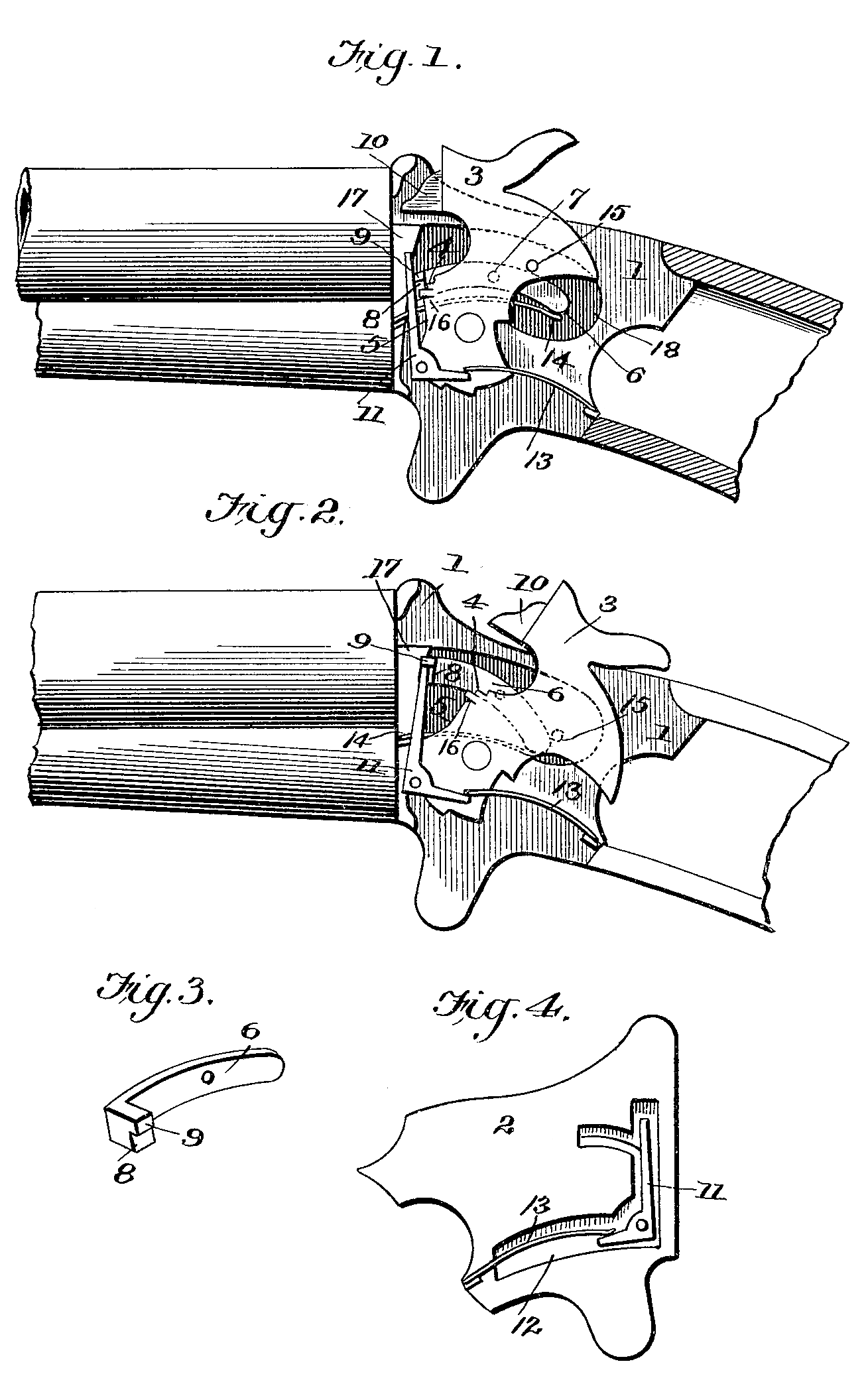
In the drawings forming part of this specification, Figure 1 is a longitudinal section of a gun-lock, showing the application of my improved safety attachment, the lever being in engagement with the hammer. Fig. 2 is a similar view with the hammer thrown back to release the locking-lever by bringing the trip lever in engagement there with. Fig. 3 is a perspective detail view of the locking-lever. Fig. 4 is a detail view of the trip-lever.
Referring to the drawings by numerals, 1 and 2 designate the side plates of the lock, between which the hammer 3 is pivoted in the usual manner and provided with a main spring and trigger of the ordinary construction. The forward part of the hammer presents a shoulder 4, from which extends downward a straight edge 5, and to one side of this hammer is located a lever 6, which is fulcrumed or pivoted in a recess 18 in the side plate 1 upon the bearing-pin 7. The forward end of the lever 6 is turned at right angles, presenting a portion S, at the upper part of which extends a lug 9. This lever is so arranged within the lock with respect to the hammer that it will fall to a position in front of the shoulder 5 when the hammer is retracted and hold the point or pin 10 of said hammer out of contact with the cartridge, serving to hold the hammer firmly against a forward movement.
In order to permit the proper operation of the hammer after it is brought to a full-cock, a trip-lever 11 is pivoted within a recess 12 therefor in the side plate 2, and the projection 9 is engaged by the upper end of said trip-lever when moved above the same, the trip-lever being automatically brought under the projection or lug by means of a flat spring 13. The locking-lever is actuated by a spring 14 to bring the forward part of the same into engagement with the hammer when the said lever is released by the trip-lever, and in or der to have the operation of these levers under the control of the hammer the latter is provided with a laterally-projecting pin 15, which engages the rear end of the locking lever when the said hammer is brought to a full-cock. The hammer is also provided with a pin 16, projecting from the front side there of, which strikes the upper end of the trip lever and moves it out of engagement with the locking-lever.
In order to relieve the strain which would otherwise be put upon the pivot or bearing pin 7 of the lever 6 when the hammer is in engagement with and presses against the right-angle portion S of said lever, I form the side plate1 with a projection or shoulder 17, whose side face is preferably flush with the left side of the hammer and which engages with the outer end of the lever 6, forming a brace for the same.
From the foregoing description, in connection with the accompanying drawings, the construction and operation of my improved safety attachment for guns and revolvers will be readily apparent, for when the hammer is brought to a full-cock the pin 15 thereof will engage the rear end of the locking-lever and elevate its forward end to an extent that will allow the trip-lever to move under the extension 9 and hold the said locking-lever out of operation, and when the hammer is released the pin 16 thereon will trip the lever 11 simultaneously with the engagement with the cartridge and permit the forward end of the locking-lever to fall into engagement with the shoulder 4 of the hammer. Now in order to bring the safety attachment into play the hammer is moved backward sufficiently to permit the locking-lever to fall into engagement with the forward end or straight edge 5 of the hammer and hold the pin or point 10 away from the cartridge. In this position the hammer is positively prevented from being moved forward, being stopped by the lever, and the only way in which it can be operated is by bringing the same to a full-cock, and thereby throw the locking-lever out of the path of the hammer.
The device forms a very simple, cheap, and effective safety attachment for guns and revolvers that does not necessitate a change in the general construction and arrangement of the lock mechanism.
Having thus described my invention, what I claim as new, and desire to secure by Letters Patent, is—
1. In a safety attachment for guns and revolvers, a locking-lever pivoted within the casing and actuated to bring its forward end in front of the hammer and a trip-lever adapted to engage the locking-lever, and hold its forward end elevated, together with projections carried by the hammer to operate the locking and trip levers, substantially as shown and for the purpose set forth.
2. In a safety attachment for guns and revolvers, the combination with the hammer, of a lever pivoted within the lock-casing and having an end which is brought in front of the hammer, a trip-lever engaging the locking-lever when the forward end of the latter is raised, springs for bringing the levers to their normal position, and pins, carried by the hammer, one of said pins lifting the forward end of the locking-lever when the hammer is brought to a full-cock while the other strikes the trip-lever when the hammer is released, substantially as shown and for the purpose set forth.
3. In a safety attachment for guns and revolvers, the combination with the hammer, of a lever pivoted in the casing and having a forward end which is brought normally in front of the hammer, a trip-lever actuated to move under the forward end of the locking lever, a pin carried by the hammer to lift the forward end of the locking-lever, and a second pin carried by the hammer to release the trip-lever, substantially as shown and for the purpose set forth.
4. In a safety attachment for guns and revolvers, the combination of a hammer having a shoulder and straight edge at its forward side, a lever pivoted to one side of the lock-casing having a lateral extension, a spring actuating said lever to force the forward end thereof downward, a pin carried by the hammer to depress the rear end of the lever when the said hammer is brought to a full-cock; together with a trip-lever, spring-actuated to move under the locking-lever when the forward end of the same is raised, and a pin or projection carried by the forward side of the hammer to release the trip-lever when the hammer is brought against the cartridge or moved to the limit of its forward movement, substantially as shown and for the purpose set forth.
In testimony whereof I have signed this specification in the presence of two subscribing witnesses.
ORLANDO ROSE.
Witnesses:
Arthur H. Griggs,
F. E. Fessenden.