
US 216
UNITED STATES PATENT OFFICE.
OTIS W. WHITTIER, OF ENIFIELD, NEW HAMPSEIIRE.
IMPROVEMENT IN MANY-CHAMBERED-CYLINDER FIRE-ARMS.
Specification forming part of Letters Patent No. 216, dated May 30, 1837.
To all whom it may concern:
Be it known that I, Otis W. Whittier, of Enfield, in the county of Grafton and State of New Hampshire, have invented a new and useful Improvement in Fire-Arms; and I do hereby declare that the following is a full and exact description thereof, reference being had to the annexed drawings of the same, making part of this specification.
The nature of my invention consists in having a metallic revolving cylinder containing any requisite number of chambers, all pointing in the same direction of the barrel, affixed at the rear of the barrel, and revolving and bringing up the chambers successively, in contact with the bore of the barrel for a discharge by means of a spring with a cam or pin in the end thereof, which runs in spiral grooves or channels made on the circumference of the revolving cylinder, connected with the percussion hammer, and turning said revolving cylinder by the movement of cocking the gun.
To enable those skilled in the art of making fire-arms to make and use my invention, I proceed to describe its construction and operation, and is as follows:
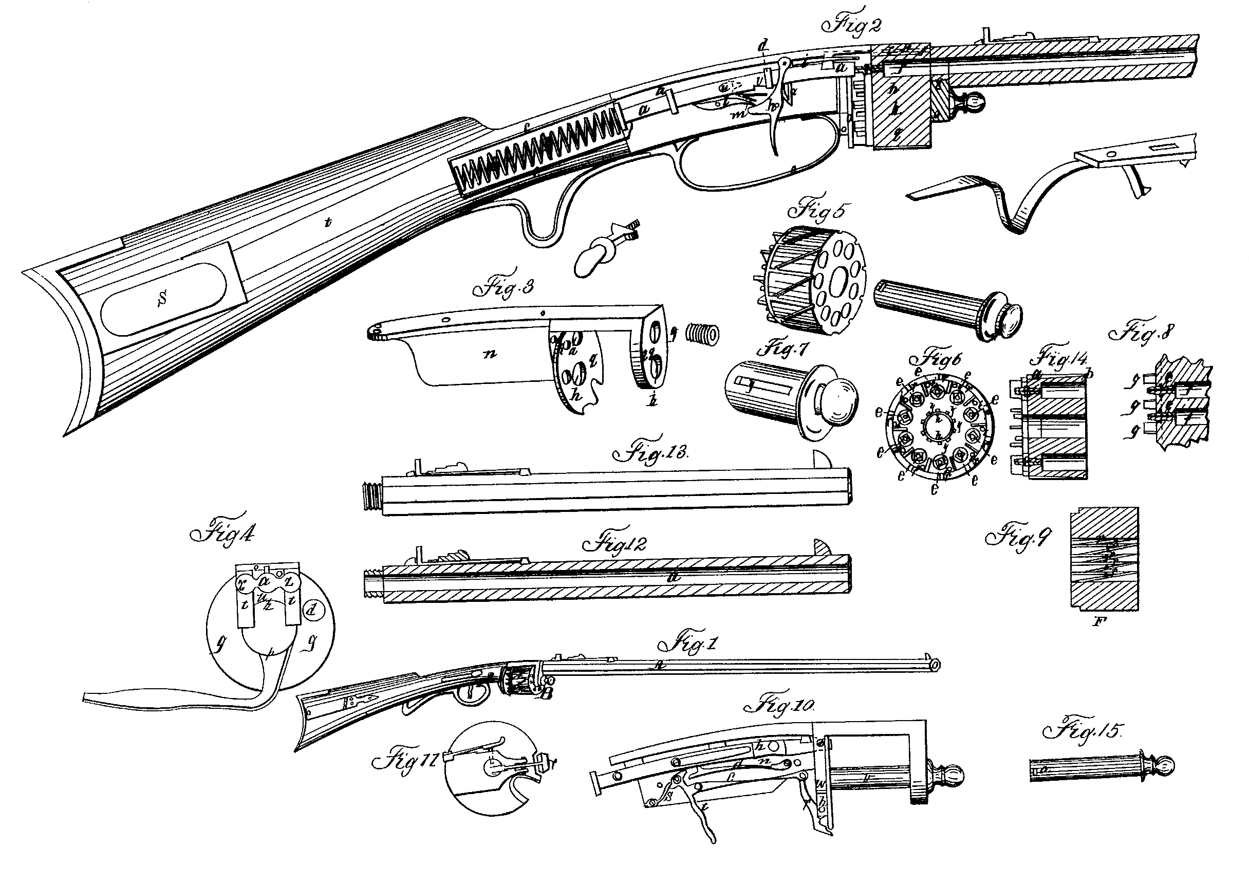
I have a main barrel, A, Fig. l, with the bore extending through from end to end. I then make any number of chambers, B, I wish, sufficient in length to hold a charge of powder and ball or shot. These chambers are fixed in a circular order, all pointing in the same direction with the main barrel, and are combined with each other by passing through heads at each end; or all of them may be bored in a solid cylindrical block of steel, iron, or other metal, as seen at f Fig. 5. Then I have a plate, O, Fig. 3, fixed to the top of the stock and extending from the stock forward, sufficient in length to cover the cylinder of chambers. I have two braces, q and q q., attached to this plate on the under side, extending downward far enough to receive a hollow spindle or pivot, Fig. 7, which I make fast by its running through said braces at each end. Then I have a hole, Fig. 3, in the forward brace, exactly opposite the highest chamber, near the top of the brace, into which I fix my main barrel by means of a screw, g, on the end of the barrel or on the brace. I make my hind brace, 1, of sufficient dimensions to cover the whole of the rear of the revolving cylinder.
In the rear of each chamber in the revolving cylinder, Fig. 6, I place the cones for the reception of the percussion-caps or primers by sinking them, so that the brace Q will not interfere with them when performing its revolutions. I have a hole, d, in the hind brace, on the right of the stock, for the convenience of putting the caps on the cones, and another hole, a, near the top of the brace, in rear of the chamber to be discharged, for the percussion-hammer, a, Fig. 2, to pass through in striking the cap, and a mortise, r, Fig. 4, directly over this, for a spring-bar, r, Fig. 2, which is attached to the hammer to pass through, in the end of which spring I have a cam or pin, A, Fig. 2, that runs in the groove on the and, r side of the plate, Fig. 3, that passes over the revolving barrel, and also runs in the spiral grooves on the circumference of the revolving cylinder, and which turns it by the movement of cocking the gun and bringing the chambers successively in contact with the bore of the main barrel.
I also construct a safety-rod, i, Fig. 2, which I attach to the trigger h, so that the pulling the trigger urges the rod i forward through a hole, i, Fig. 3, in the rear brace successively into the holes i, Fig. 6, in the revolving cylinder, which are brought up successively by the revolutions of the revolving cylinder. These holes I make in a circle concentric with the circle of cones, and are placed equidistant between each two of them, and make the hole in the brace to meet them in return, so that in case the cylinder is not in its proper place the safety-rod cannot enter the aperture, and therefore will not admit the trigger to act upon the dog, and a discharge calm not take place until the revolving cylinder is in its right position. I likewise make as many spiral grooves, r, Fig. 5, on the outside of the revolving cylinder as there are chambers in it running diagonals from the forward end of one chamber to the rear end of the next, so that in cocking the piece the pin A, Fig. 2, in the spring hereinbefore described will run in this groove from the fore end of one chamber to the rear of the next, thus causing it to move one chamber at a time. I also make as many more grooves, s, Fig. 5, running in a parallel line with the chamber, and starting from the rear of each spiral or diagonal groove and of equal depth at the commencement, but gradually approaching the surface at the forward end of the chambers, so that the pin A on the spring r, Fig. 2, when firing the gun, is thrown forward up the parallel groove until it drops over into the next spiral groove, and is in readiness to bring up the next chamber, as before, and so on in succession.
The like revolutions of the revolving cylinder may be obtained by having similar grooves on the inside of the revolving cylinder, as shown in Fig. 6 at y, and by having a slot, y, in the hollow spindle, Fig. 7, through which the pin on the spring before described may operate in the grooves, the spring in that case being attached to the under side of the hammer.
I construct the lock in the following manner: I have a curved hammer, a, Fig.2, attached to a perpendicular plate,n, connected with the plate in by means of staples d d. The hammer is thrown forward by a folding or spiral spring, b b, in the rear of the hammer. On the top of the hammer a, at or near the fore end, I fasten the spring r, that holds the pin A, which moves in the grooves r s, Fig. 5, as before described. The fore end of the hammer is fixed in such a manner that when thrown forward it strikes the cap. I fix the dog l, Fig. 2, in the usual form, and it catches in a notch, v, on the under side of the hammer when it is drawn back by means of a knob, d, on the right side of the stock. The dog is acted upon by a trigger, h, in the usual manner; k, feather-spring for throwing back the safety-rod; m, feather-spring for pressing the dog into the notch v when the hammer is drawn back; c c, metallic box, in which the folding spring is placed.
Fig. 8 represents a section of two of the chambers, showing the manner of inserting the cones for the percussion-caps; e e, the cones; f f, the chambers; g g, partitions between the cones, which may be used instead of sinking the cones in the face of the revolving cylinder.
Fig. 4 represents the guard and rear plate; o, the guard; q, rear plate. The letters a d i n q r t p correspond to the same letters in Figs. 1, 2, 3. z z are tubes to suffer the explosion from the vent to escape when the chamber is not used.
Fig. 2 represents a section of a gun of full size, in which t is the stock, and s the patch-box.
Fig. 9 represents a sectional view of the inside of the aperture for the spindle, grooved in a similar manner to the outside of the cylinder, as before described; r, rectangular grooves; s, diagonal grooves.
Fig. 10 is a view of lock, showing another form of safety-rod; r, safety-rod turning on a pivot, p, in the rear plate, attached to the trigger t by a connecting-rod, c, d, the spring-dog; h, hammer; n, notch in the hammer, into which the dog enters; s, spring of the trigger; v, spindle; c, spring-stop to secure the spindle.
Fig. 11 is a view of rear plate, showing the end of spindle v and the stop x (represented by dotted lines)passing through the rear plate, and entering the spindle. r is the safety-rod.
Fig. 12 represents a section through the barrel, showing the manner of rifling it. a is the bore.
The mode of rifling the barrel used by me differs from the common mode in an essential point—namely, in commencing at the breech with a gentle twist or spiral curve, and gradually increasing it toward the muzzle, where it receives a shorter twist, by which method the ball receives a rapid whirling motion when thrown from the bore, which is essential to correct firing.
Fig. 13 is a view of the outside of the barrel.
Fig. 14 represents a longitudinal section of the cylinder, showing the form of the rectangular groove, and the commencement of the diagonal groove where they unite and form a continuous groove around the cylinder, a is a rectangular groove; b, end where it unites with the diagonal groove.
Fig. 15 represents the spindle, in which a is the aperture for the spring-stop to enter.
The invention claimed by me, the said Otis W. Whittier, and which I desire to secure by Letters Patent, consists in the following items, viz:
1. In the method of turning the cylinder of chambers by means of a pin, A, Fig. 2, attached to the horizontally-sliding hammer a, driven when a discharge is made along one of the grooves on the surface of the cylinder, running parallel with its axis over the center of one of the chambers, and falling at the end into an oblique groove, where they meet and form a continuous groove, and when the hammer is drawn back to be cocked said pin being in one of the grooves running diagonally or obliquely from the forward end of the rectangular groove just mentioned back to the rear end of the next rectangular groove formed over the center of the next chamber, which causes the cylinder to turn the exact distance required to bring the next chamber in a true line with the bore of the barrel for another discharge, and so on in succession.
2. In making the rectangular parallel groove deep at the rear end and shallow at the forward end, to cause the pin to fall from one of the rectangular into one of the diagonal grooves to shift the chamber.
3. The spring-bar r and pin A, Fig. 2, attached to the hammer for turning the cylinder, in combination with before-described grooves or chambers.
4. The safety-rod or guard-pin i, attached to the trigger, which at every discharge is driven into a corresponding aperture in the rear end of the chamber for securing it when in its proper place for firing, but should the cylinder not be in its proper position will strike against the solid part of it, and thus prevent the trigger acting upon the dog.
OTIS W. WHITTIER,
Witnesses:
Wm. P. Elliot,
Wm. Bishop.