
US 200794
UNITED STATES PATENT OFFICE.
OWEN JONES, OF PHILADELPHIA, PENNSYLVANIA.
IMPROVEMENT IN REVOLVING FIRE-ARMS.
Specification forming part of Letters Patent No. 200,794, dated February 26, 1878; application filed January 28, 1878.
To all whom it may concern:
Be it known that I, OWEN JONES, of Philadelphia, county of Philadelphia, and State of Pennsylvania, have invented new and useful Improvements in Revolvers, and I do hereby declare that the following is a full and exact description of the same, reference being had to the accompanying drawings, and to the letters of reference marked thereon.
This invention relates to that class of revolvers which are provided with mechanism for extracting the cartridge-shells, and is an improvement upon my previous patents of June 20, 1876, No. 179,026, and April 10, 1877, No. 189,360.
Its novelty consists, mainly, first, in the combination of the lever-barrel, by means of which the cylinder is actuated, with the cylinder, the parts being directly connected together without independent intermediate parts second, in the combination, with the tilting lever-barrel, of a movable stop adapted to arrest the tilting barrel at the end of its normal movement for discharging the cartridges, and, also, when properly actuated, to permit further movement for the purpose of allowing the cylinder to be removed from the centerpin; and, third, in the combination, with the lever-barrel, of a catch of peculiar construction; and it consists, further, of certain details of construction, which, in connection with the foregoing, will be fully described hereinafter.
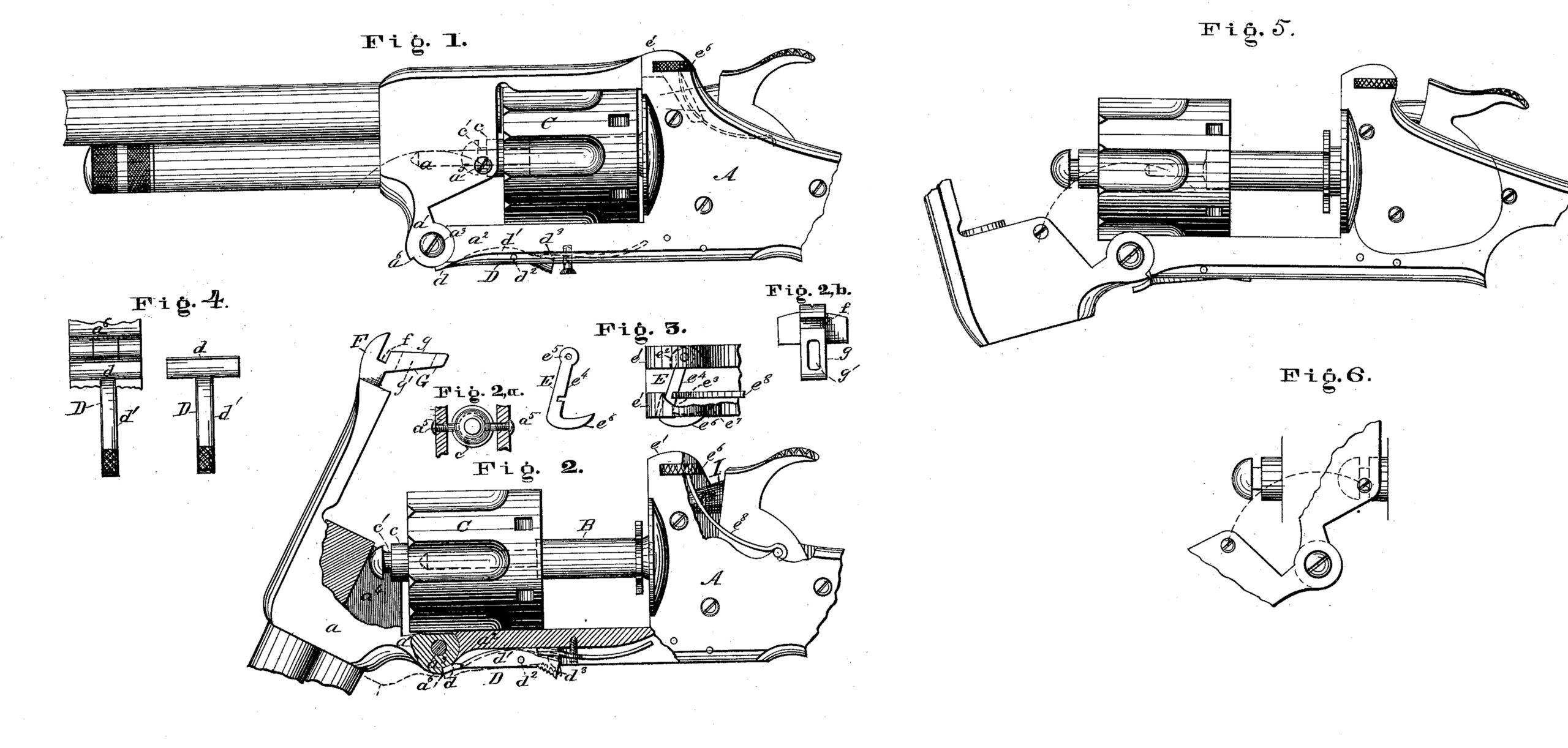
In the drawings, Figure 1 represents a partial side elevation of a revolver having my improvements applied thereto, the barrel being shown in its closed position. Fig. 2 represents a similar view, with the barrel tilted to discharge the cartridges. Figs. 3 and 4. represent detail views of various parts. Fig. 5 represents a partial side elevation with the barrel tilted beyond its normal limit for discharging the cartridges, for the purpose of removing the cylinder, and Fig. 6 a partial side elevation, showing the relative movement of the cylinder-projection and lever-barrel studs.
To enable others skilled in the art to make and use my invention, I will now proceed to describe the same fully, and the manner of operation.
The main portions of the revolver, not claimed as new in this application, may be constructed in a similar manner to the corresponding parts described and illustrated in my previous patents, before referred to, or in any other proper manner. The novel parts, upon which this application is based, will be described, for convenience and clearness, under separate heads, as follows: First, the lever-barrel and cylinder; second, the lever-barrel and movable stop; and, third, the lever-barrel and catch.
I. The lever-barrel and cylinder. –a, Figs. 1 and 2, represents the lever-barrel provided with the downwardly-extending portion a, hinged to the lower bar or strap a2 by means of the pivot-pin a3, as shown. a4, Fig. 2, represents a recess formed in the rear end of the barrel-block, and a5 a5, Figs. 1 and 2, studs or pins projecting from the wall on either side, as shown. These studs may either form a solid portion of the barrel block, or consist of screws inserted from the outside, as shown. The latter construction is preferred, because the screws before insertion can be case-hardened to make them more durable under wear. When inserted in place, however, they form practically a solid portion of the barrel.
B represents the center-pin, rigidly secured at its rear end to the frame, as shown in my patent, No. 189,360.
C represents the cylinder, constructed generally in any proper manner, but essentially provided in front with an extended hollow sleeve, c, having a single annular groove or recess, c’, as shown.
The cylinder and lever-barrel, properly united together, are represented in Fig. 1.
Union of the parts is effected, it will be observed, by the studs a5 a5 of the barrel and the sleeve c of the cylinder, the former resting in the annular groove of the latter, as shown. By means of this construction the parts are so united that the cylinder is compelled to move in a longitudinal direction with the barrel when the latter is tilted, but is free to revolve upon its center-pin without interference. The connection is such, also, that the necessary play incidental to the union of two parts moving on different lines is obtained in a simple manner, the studs a5 a5 rising and falling, as the barrel is tilted, in the annular groove of the horizontally-moving cylinder, to describe the arc of a circle struck from the pivot-pin a3 as a center. The advantages of this special construction will be readily understood. The barrel and cylinder are attached directly together without intermediate auxiliary connecting devices, in consequence of which the number of parts is reduced, and the arm is much simplified and improved;
II. The lever-barrel and movable stop–a6, Fig. l, represents a stop-projection formed upon the part a1 of the barrel. D, Figs. l, 2, and 7, represents a movable stop, consisting of a transverse plate, d, extending beyond the solid portion of the lower bar or strap a2, and partially over the hinge, as shown in Fig. l, and a longitudinal lever-arm, d1, lying in a proper recess of the bar, the latter being secured in place by a pivot-pin, d2, as shown. d3 represents an extended portion of the cylinder bolt spring, by means of which the stop-plate is ordinarily held in its normal position, as shown in Fig. 1.
The operation is substantially as follows: When the lever-arm all of the stop D is not moved, and the plate d consequently remains in its normal position, the lever-barrel, when tilted, will be arrested at the end of its normal movement for discharging the cartridge shells by the contact of its stop projection a6 with the plate d, as shown in full lines, Fig. 2. When the parts are in this position, the cylinder is securely held upon the center-pin, and cannot be removed. When, however, the lever-arm d1 is properly actuated, the plate d will be thrown outward beyond the line of movement of the stop-projection a6 of the part a1 of the barrel, as shown in Fig. 5, and hence the latter, when the barrel is tilted, will not engage with the same at the vend of its normal movement for discharging the cartridge-shells. The stop-plate is thus made inoperative for the time being, and hence the tilting movement of the barrel may be continued until the studs a5 a5 move out of the annular groove of the cylinder, as shown in Figs. 5 and 6, and release the same, so that it may be removed from the center-pin. The cylinder is readily replaced, when desired, by sliding the same upon the center-pin, and tilting the barrel in such manner as to cause its studs to engage with the groove of the sleeve c. The advantages of this construction will be readily understood. The cylinder is positively held against accidental displacement, and yet is removed with great facility when desired.
III. The lever-barrel and catch–e1 e1, Figs.1 and 3, represent ears, projecting upward from the side plates of the frame A, each of which is provided with a slot, e2 e3, as shown.
E represents a catch-piece consisting of a transverse bar, e4, having at one end a pivot opening, e5, and at the other an angular thumb-piece, e6, as shown. This catch-piece is represented in position in Figs. 1 and 3. One end, it will be observed, is pivoted in the slot e2, while the other end extends through the elongated slot e3, as shown. The thumbpiece is curved upon its inner side to correspond with the curvature of the recess e7, in which it moves.
e8 represents a spring, of any proper construction, by means of which the catch-piece, after being actuated, is returned to its normal position.
F, Fig. 2, represents a projecting portion of the inner end of the barrel-block, extending rearward in a horizontal direction, which is provided with the horizontal recess f, Figs. 2, 2b, adapted to receive the transverse bar of the catch-piece, as shown.
G represents a projecting portion extending downward at an angle in such manner as to form an inclined plane, g.
g’ represents an opening extending from front to rear through the portion G, which is adapted to receive the hammer-nose I when the latter is in position to explode the cartridge.
The operation will be readily understood. When the lever-barrel, after having been tilted to discharge the cartridges, or for other purpose, is re-tilted to return it to its normal locked position, the inclined face of its projection G will come in contact with the pivoted catch e4, and turn the same on its pivot out of the line of the projections movement, so that proper space is afforded for its passage. When the proper point is reached, however, the horizontal recess f will be opposite the transverse catch-piece, and the latter, having now been released by the passage beyond it of the projection G, will be moved into the same by the reaction of the spring e8, and thus securely lock the barrel in place. The opening g’ in the projection G is so arranged relatively to the hammer-nose that the latter, when in position to explode the cartridge, bears against its lower edge, as shown in dotted lines, Fig. l.
From this construction and arrangement it follows that the cartridge cannot be exploded unless the projection G, and, consequently, the barrel attached thereto, is in its proper locked position. If, however, the barrel is nearly but not entirely closed, the same will be brought to its proper locked position by the descent of the hammer before the explosion takes place, the inclined face of the latter acting upon the projection G to force it down into its proper place.
The advantages of the described construction will be readily understood. The catch is exceedingly simple in its construction and operation, and yet it possesses great strength. It extends entirely across the projection of the barrel, and is strongly held at each end against strain. The cartridges cannot be exploded by the hammer-head unless the barrel is in its locked position.
Having thus fully described my invention, what I claim as new, and desire to secure by Letters Patent, is–
1. The combination of the lever-barrel a with the cylinder C, substantially as described, the barrel having an independent pivot-connection, a3, and being directly united to the cylinder at the center of the same, without intermediate connections, for the purpose of giving movement to the cylinder without strain upon the center-pin, substantially as described.
2. In combination with the lever-barrel having an independent pivot-point, a3, and the studs a5, the cylinder C, having the central projection c and annular groove c’, substantially as described.
3. The combination of the following elements: a tilting lever-barrel, a removable cylinder, and a movable stop, adapted to permit the movement of the lever-barrel beyond its normal limit, for the removal of the cylinder, substantially as described.
4. In combination with the pivoted catch, held down at each end, substantially as described, the lever-arm having a projecting portion adapted to extend beneath the catch, as described.
5. In combination with the recessed arm of the lever-barrel, the pivoted catch-piece, extending across the arm, and held down at each of its ends, as described.
6. In combination with the recessed arm and catch-piece, the projection G and hammer-head, as described.
This specification signed and witnessed this 10th day of January, 1878.
OWEN JONES.
Witnesses:
E. A. CORBIN,
H. G. GOODRICH.