
US 53548
UNITED STATES PATENT OFFICE.
PROSPER POLAIN, OF BRUSSELS, BELGIUM.
IMPROVEMENT IN REVOLVING FIRE-ARMS.
Specification forming part of Letters Patent No. 53,548, dated March 27, 1866.
To all whom it may concern:
Be it known that I, PROSPER POLAIN, of Brussels, in the Kingdom of Belgium, have invented certain new and useful Improvements in Sliding Revolvers with Isolated Chambers; and I hereby declare that the following is a full, clear, and exact description of the same, reference being had to the accompanying drawings.
This invention relates to improvements in revolving fire-arms, and its main features are as follows:
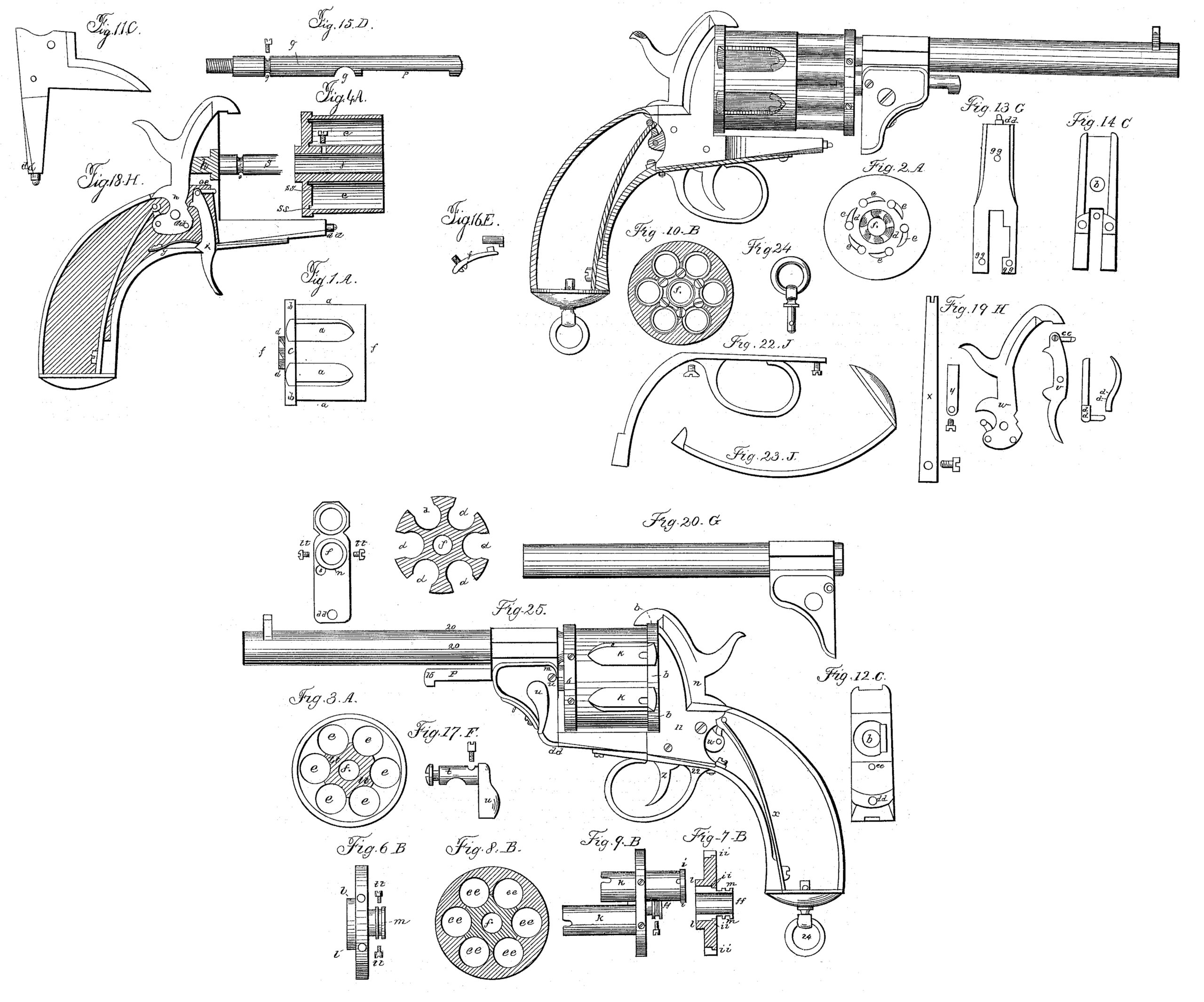
In the cylinder of the revolving fire-arm the requisite number of chambers are bored, each of these chambers being entirely separated from the others. Within these chambers are fitted sliding cartridge-tubes or small barrels for receiving the charges, which tubes are secured by their upper ends to a disk. The latter is pierced with circular holes, in diameter corresponding to the chambers in the cylinder. At the bottom of the cylinder-chambers are countersunk grooves, in which the ends of the cartridge-tubes fit or are embedded when the pistol is ready to be fired. The fouling which often interferes with the working of revolving fire-arms is thus prevented, and all communication of fire from one tube to another is rendered impossible.
Lateral apertures are made in the cylinder, opening from the outside into each chamber, each opening being widest at the base of its cylinder-chambers, where it commences, and thence extending nearly the whole length of the chamber, gradually tapering to a point. It is intended that the Lefaucheux or pin-cartridge should be used with this pistol. Through the openings just mentioned the cartridges are inserted in and withdrawn from the cartridge tubes. These openings also take the place of a clearer or extractor. When the pistol is unloaded and the cartridge-tubes are drawn out of the cylinder-chambers the pins of the cartridges catch in the upper ends of the openings, and the cartridge-cases are thus extracted from the tubes.
To enable others skilled in the art to understand and to use my invention, I will now proceed to describe it.
In the drawings, Figure 1, A is a cylinder, made in one piece, in which several chambers are bored, being closed in the rear by the breech-plate b b. In the center of the rear face of the breech-plate is a six-toothed ratchet, d. The lateral openings a in each cylinder-chamber are those through which the cartridges are placed in or withdrawn from the charge tubes. The center of the cylinder and of the ratchet d is perforated, as seen at f, to receive the central rod or spindle, g, Fig. 4, A. At the bottom of the chambers of the cylinders are the countersunk grooves s s, in which the ends of the charge-tubes fit when the pistol is ready to be fired.
On the rear face of the breech-plate, Fig. 2, A, are seen the locking-recesses c c, by means of which the cylinder is held firmly in position when the piece is to be fired.
Fig. 3 represents the division of the chambers e e of the cylinder A, and also the recessed part l l, which receives the re-enforcement l of the disk, Fig. 6, as hereinafter described.
Fig. 4 represents a longitudinal section of the cylinder.
Fig. 5 gives a view of a transverse section of the cylinders, where the lateral openings a are shown.
The disk and its sleeve, Fig. 6, B, are, like the cylinder, composed of one piece of metal. The disk has several holes, e e, Fig. 8, corresponding to the chambers of the cylinder, in which holes are fastened the charge-tubes K, Fig. 9. The tubes are provided with rims or flanges i, Fig. 9, which fit into recesses i i in the face of the disk. The charge-tubes are held in place by means of screws inserted between the sleeve f f Fig. 10, and the bores of the disk e e, Fig. 8. The heads of the screws are sunk in recesses made in the disk, so as not to project above the plane of the disk. To the rear of the disk is attached a re-enforcement, l, which serves to give a better hold to the screws used in fastening the cartridge tubes. This re-enforcement l fits into a corresponding recess in the cylinder l l, Fig. 3. Other little screws are placed in the periphery of the disk for the purpose of holding the cartridge-tubes more securely. Welding can be substituted in place of this method of securing the cartridge-tubes. Fig. 9 represents two of these tubes, one fixed to the disk and the other detached from it.
A groove, m, is made on the sleeve f f of the disk, Figs. 7 and 9. This part of the sleeve is lodged in the rear end of the brace of the barrel, Fig. 21. Two little screws, t t, Fig. 21, fit in the groove, being inserted therein through the sides of the brace. By this arrangement the disk is permitted to revolve freely upon the central spindle, and at the same time is firmly connected with the main barrel.
The central spindle, D, Fig. 15, is screwed to the recoil-plate C, Fig. 11, at the point h, Fig. 12. A little groove, v, Fig. 15, is made near the base of the spindle. From the interior of the cylinder A, Fig. 4, a screw is inserted in this groove, intended to hold the cylinder in place, at the same time leaving it free to revolve upon its axis, if desired. On the upper part of the spindle is a longitudinal groove, p, Fig. 15, in which the sliding pin, Fig. 16, works. About midway on the spindle is a slot or notch, g, Fig. 15, in which the lever-key fits, and thus locks the pistol.
Fig.16 represents the guide pin, which serves to guide and maintain the barrel in a horizontal position. It is composed of a small pin, , which fits in the longitudinal groove p of the spindle D, and of a spring, s, fastened by means of a screw to the brace. This spring, slightly curved, is furnished on its upper end with a stud which penetrates the shoulder, and, fitting in the sliding pin r, holds it firmly against the face of the groove.
The key F, Fig. 17, is composed of an eccentric, t, which is worked by means of an exterior lever, u. This lever being raised the disk, with its cartridge-tubes connected with the main barrel, as has been above described, slides backward or forward on the spindle D. When, on the other hand, the lever is pressed down the eccentric t is forced into the notch or slot g, Fig. 15. The pistol is thus locked and all the different parts of the piece firmly held in position. The movement of the lever is limited by a little screw, v, placed in the rear face of the brace. The lock is composed of a cock, Fig. 19, w, a mainspring, x, a guide for the cylinder, and its spring a a, a trigger, z, and cam-like projection or catch, e e, and a little trigger-spring, y. The catch e e is fastened by a screw to the upper end of the trigger. Immediately opposite the catch is an aperture, e e, Fig. 12, made in the recoil-plate, facing the locking-recesses in the breech-plate of the cylinder C, Fig. 2. Each time that the cock or hammer is raised the catch is forced forward through the opening c c into the locking recesses, thus stopping the cylinder and holding it in position. The catch only quits the notch when the pressure is removed from the trigger.
Fig. 11 is a profile view of the recoil-plate. In Fig. 12 is shown the face of the recoil-plate. In the center, h, is the openings, in which is lodged the guide of the cylinder, Fig. 10, a a, and of the six-toothed ratchet, which is on the cylinder. Below is the aperture c c for the passage of the trigger-catch. On the lower part of the plate is the tenon d d for joining it to the brace.
Fig. 13 represents the bottom of the recoil plate. The holes g g are for the screws used to secure the trigger-guard to the plate. Fig. 14 is a rear view of the recoil-plate. Fig. 20 is a profile view of the main barrel.
Fig. 21 represents the rear face of the shoulder of the barrel. In the center is the hole f for the passage of the central rod or spindle. Around this hole there is a recess, n, intended to contain the part m of the sleeve of the disk. The two screws t t (represented in this figure) are those which pass through the side faces of the brace, fitting in the groove on the sleeve of the disk. At the point v, Fig. 17, is a hole in which is placed the screw which limits the movement of the lever.
Fig.22 represents the trigger-guard; Fig. 23, the handle of the pistol, and Fig. 24 the ring in the butt, by which the pistol may be suspended by a strap. Fig. 25 represents the pistol adjusted and closed, and Fig. 26 represents the same opened.
In revolving fire-arms I claim the combination of the following elements:
1. A revolving cylinder whose chambers are provided with lateral openings and counter sunk grooves, as set forth.
2. A cluster of charge-tubes capable of revolution with the revolving cylinder and of sliding upon its axis, as herein described, the whole operating so that the fire-arm may be loaded or the charges withdrawn without disengaging the sliding charge-tubes from their respective cylinder-chambers.
In testimony whereof I have signed my name to this specification before two subscribing witnesses.
PROSPER POLAIN.
Witnesses:
L. POLAIN,
RÜBMYERS.