
US 391214
UNITED STATES PATENT OFFICE.
REINEHARD T. TORKELSON, OF WORCESTER, MASSACHUSETTS, ASSIGNOR TO IVER JOHNSON, OF SAME PLACE.
REVOLVER.
SPECIFICATION forming part of Letters Patent No. 391,214, dated October 6, 1888. Application filed August 1, 1888. Serial No. 281,680. (No model.)
To all whom it may concern:
Be it known that I, Reinhard T. Torkelson, of the city and county of Worcester, and State of Massachusetts, have invented certain new and useful Improvements in Revolvers; and I do hereby declare that the following is a full, clear, and exact description thereof, reference being had to the accompanying drawings, forming a part of this specification, and in which—
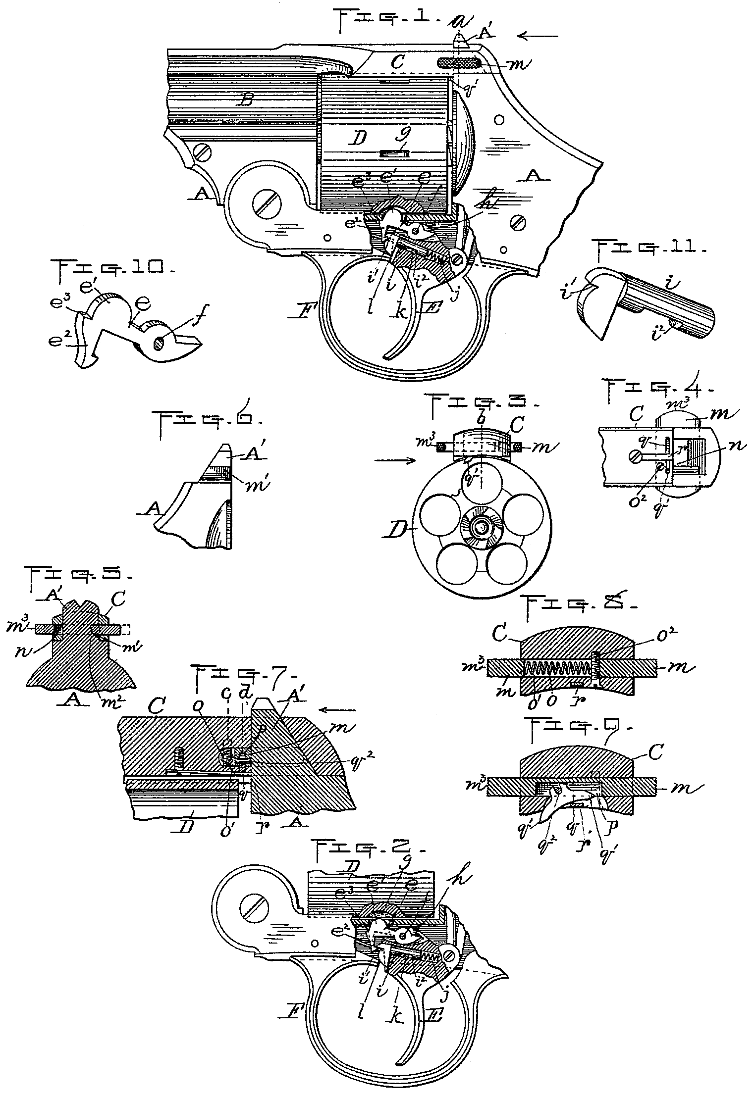
Figure1 represents a side view, partly in section, of so much of a revolver as is necessary to illustrate my improvements. Fig.2 is a view of the lower part of Fig. 1, showing my improved cylinder stop and lock device, hereinafter described, disengaged from said cylinder in Fig. 1, the various parts being shown in their normal positions with the cylinder locked. Fig. 3 is a rear end view of the cylinder and barrel-strap, showing how said cylinder is held in position longitudinally by my improved device for that purpose, also hereinafter described. Fig. 4 is a bottom view of the rear end of the barrel-strap with my improvement applied thereto. Fig. 5 is a transverse section taken on line a, Fig. 1. Fig. 6 is a side view of the catch-post and upper part of the frame of my improved revolver. Fig. 7 is a central longitudinal section, upon an enlarged scale, taken on line b, Fig. 3. Figs. 8 and 9 are transverse sections, upon the same enlarged scale as Fig. 7, taken at the points indicated by lines c d, same figure; and Figs. 10 and 11 are detached perspective views, also upon an enlarged scale, of parts relating to my improved cylinder stop and lock device previously referred to.
My invention consists of improvements in the mechanism for stopping and locking the cylinder against rotary motion at the end of each partial revolution thereof, for holding said cylinder in position longitudinally and for locking the barrel-strap to the catch-post, as hereinafter more fully set forth.
To enable those skilled in the art to which said invention appertains to obtain a full and clear understanding thereof, I will now proceed to describe it more in detail.
In the drawings, A represents part of the frame, B part of the barrel, C the barrel strap, D the cylinder, E the trigger, and F the trigger-guard, of the revolver.
My improved device for stopping and locking the cylinder against rotary motion, as aforesaid, is connected with the trigger E, and is constructed in the following manner: A stop-lever, e, is hinged near its rear end, at f, to the upper end of said trigger, preferably in a vertical slot formed therein. Said stop-lever is provided upon the top of its front end with an upwardly-turned flange, e’, adapted to engage with the usual peripheral notches, g, in the cylinder, and with a suitable spring, h, for forcing up said forward end, which in this instance is arranged between the top of its rear end and the frame A. The lever is also provided with a hook, e^2, projecting downward from its front end, adapted to engage with a shoulder or notch, i’, on the front end of the bolt i, and is further, preferably, provided with a shoulder or notch, e^3, adapted to bear against the frame or some stationary point to control its upward movements. Said notch e^3 is not essential, however, as the lever may be made to strike a stationary point at any convenient place in front of its pivot to effect the same result, and I therefore do not limit myself thereto.
The bolt i is fitted in a longitudinal opening in the trigger under the stop-lever e, and in addition to the shoulder or notch i’ previously referred to, which is formed on its forward end, it is provided with a suitable spring, j, for exerting a forward pressure thereon, said spring in this instance being fitted in the bolt-opening and adapted to bear against the rear end of said bolt. The forward movements of the bolt are controlled by forming a slot therein to produce a shoulder, i^2, which bears against a fixed transverse pin, k, in the trigger, and said bolt is forced back to disengage it from the hook e^2 on lever e by making its forward end under the notch i’ convex shaped, so as to act as a can against the stationary point L when the trigger is pulled back, and thus produce the above-described result.
As various well-known ways may be adopted for controlling the forward movements of the bolt, I do not limit myself to the construction Shown and described.
The lever e is in this instance shown as being hinged to the trigger-pivot; but I do not limit myself thereto.
The other features of my invention combine in one device means for holding the cylinder in position. longitudinally, as well as for locking the barrel-strap C to the catch-post A’, and which device will now be described. Said barrel-strap C is provided with the usual vertical opening to receive the catch-post A’, and also with a transverse opening to receive the bolt m, and said bolt is in turn slotted vertically, as shown at n, to allow the catch-post to pass up through when the bolt is in position in the barrel-strap, and is also provided with a suitable spring, o, for forcing said bolt at one side of its slot, into a longitudinal groove, m’, formed in one side of the catch-post, and thereby fastening the barrel-strap to said catch-post. The spring o is in this instance arranged transversely in a slot or opening, o’, in the bolt. It is held in position between said bolt and a vertical screw, o^2, which, being passed up through said slot or opening in the bolt, serves to hold said bolt from being forced out of the strap by its spring. The strap is fastened to the catch-post by forcing the same down over said catch-post, as usual, the bolt being thereby forced to one side until arriving opposite the groove m’, when it is sprung into the same and securely held in position, said operation being facilitated by rounding the inner edge of the bolt, as shown at m^2, so that it may readily slip over the top edge of the post, and by making the groove m’ in said post with a square shoulder at its upper edge, as shown in Fig. 5, to hold the strap as aforesaid.
Between the openings o’ and n in bolt m is formed a vertical transverse slot, p, which is also extended down through the barrel-strap (see Figs. 7 and 9) to receive a centrally-pivoted lever, q. The vertical slot and said lever are arranged to come just back of the cylinder, and the lever is tilted to bring one or the other of its ends q’ below the barrel-strap, as shown in Figs. 3 and 9, to hold the cylinder by the operation of the bolt m, the lever being pivoted at q^2 to the bolt, also made with its lower edge concave in shape, and a central fixed bearing, r, arranged under the same to tilt it in first one direction and then the other by the forward and back movements of said bolt against the same. In said Fig. 9 the bolt and lever are shown in their normal positions with one of the ends g’ in position for holding the cylinder as aforesaid. When it is desired to remove said cylinder, the bolt is pushed in by pressing on the end m^3 thereof to unlock the strap from the catch-post, and upon said strap being swung up said bolt is pushed in again part way to bring the lever q into a horizontal position with both of its holding ends q’ above the cylinder, thus admitting of said cylinder being readily withdrawn from the spindle upon which it turns.
For the purpose of convenience in fitting the tilting-lever q in position, I prefer in practice to make the upper end thereof fork-shaped to fit its pivot q^2 and form the stationary bearing r by fitting and fastening a separate strip or plate in a suitable recess in the under side of the barrel-strap, as is best shown in Figs. 4 and 7. I do not, however, limit myself thereto.
Having described my invention, what I claim therein as new, and desire to secure by Letters Patent, is—
1. In a fire-arm, the combination of the cylinder D, having the peripheral notches g, with the lever e, hinged near its rear end to the trigger, having the upturned flange e’ in front of its pivot adapted to engage with said cylinder-notches, and a suitable spring for forcing up its forward end, also having a downwardly-projecting hook, e^2, at or near its forward end, adapted to engage with a shoulder or notch, i’, on the front end of a bolt, i, as well as means for controlling the upward movements of said forward end, said bolt i fitted in a longitudinal opening in the trigger under ever e and having a suitable spring for forcing it forward, also having a convex-shaped cam on its front end adapted to bear against a stationary point, l, to force said bolt back when the trigger is pulled back, and means for controlling its forward movements, and trigger E, substantially as and for the purpose set forth.
2. The combination of the frame, trigger, and cylinder of a fire-arm with a cylinder stop and lock device, consisting of a lever hinged near its rear end to the trigger and having an upturned flange in front of its pivot, adapted to engage with the usual peripheral notches in the cylinder, also having a downwardly-projecting hook at or near its forward end, and a spring for forcing up said forward end, also a notch or its equivalent for controlling its upward movements, substantially as described, and a bolt arranged under the aforesaid lever in a longitudinal opening in the trigger having a notch or shoulder on its front end adapted to engage with the hook on the aforesaid lever, also having means for forcing it forward, and a notch or its equivalent for controlling its forward movements, and, furthermore, having its front end under the hook-notch aforesaid made convex in shape and adapted to bear upon a stationary point, whereby when the trigger is pulled back the lever is first pulled down and then released and allowed to be sprung up again, substantially as shown and specified, for the purpose stated.
3. In a fire-arm, the combination of a lever hinged at or near its rear end to the trigger, having an upturned flange at its front end adapted to engage with the usual cylinder, peripheral notches, also having a downwardly projecting hook or its equivalent at or near its forward end, and a spring for forcing up said forward end, also a notch or its equivalent for controlling the upward movements thereof, substantially as described, with means for first drawing down the flanged and hooked end aforesaid of the lever to disengage it from the cylinder, and to then release the same to allow it to be sprung up to lock said cylinder by pulling back the trigger, consisting of a bolt arranged in a longitudinal opening in said trigger under the lever, having a notch at its forward end adapted to engage with the lever-hook, and a convex-shaped cam under said notch adapted to bear against a suitable stationary point when the trigger is operated, as aforesaid, also having a spring for forcing said bolt forward, and a notch or its equivalent for controlling its forward movements, substantially as set forth.
4. In a firearm, the combination, with the barrel-strap and the catch-post having a longitudinal groove in one of its outer sides, of the bolt m, having a vertical slot or opening to receive said catch-post, and means for exerting an end-pressure thereon, as well as for controlling its longitudinal movements, and a tilting-lever, q, hinged to said bolt in a vertical slot formed therein and in the barrel strap just back of the rear end of the cylinder when said cylinder is in its normal position, said lever being made concave upon its lower edge and having a fixed bearing under the same, substantially as and for the purpose set forth.
5. The combination of the tilting-lever q, arranged in a vertical slot in the barrel-strap and having its lower edge made concave in shape, with a fixed bearing engaging with said concave edge, and a transverse bolt or its equivalent fitted in a transverse opening in said barrel-strap, having a vertical slot to receive the aforesaid lever, means whereby it may be hinged thereto, and means for exerting an end pressure against said bolt as well as for con trolling its longitudinal movements, substantially as and for the purpose set forth.
6. The combination, with the cylinder of a fire-arm, of a device for holding the same in position upon its spindle longitudinally, consisting of a hinged tilting-lever arranged in a vertical slot formed in the barrel strap, whose lower edge is made concave in shape and adapted to bear against a fixed point on said barrel-strap, and a spring slide-bolt arranged transversely in the barrel-strap, to which the upper end of said lever is connected, whereby it may be moved or slid sidewise to bring one or the other of its ends below the bottom of the barrel-strap, and whereby said lever may be held in its normal position with one of its ends tilted down below the bottom of said barrel-strap, substantially as shown and specified.
REINHARD T. TORKELSON.
Witnesses:
W. B. Nourse,
Lucius. W. Briggs.