
US 179633
UNITED STATES PATENT OFFICE.
ROLLIN WHITE, OF LOWELL, MASSACHUSETTS.
IMPROVEMENT IN REVOLVING FIRE-ARMS.
Specification forming part of Letters Patent No. 179,633, dated July 4, 1876; application filed April 12, 1876.
To all whom it may concern:
Be it known that I, ROLLIN WHITE, of Lowell, Middlesex county, Massachusetts, have made certain Improvements in Revolving Fire-Arms, of which the following is an accurate specification:
The object I have in view is to simplify, make more cheaply and more effective, the mechanism by which a fire-arm is discharged, by which the cylinder is rotated, and by which the cartridge is extracted; and my invention herein consists, principally, in the novel construction and combination of parts by which the above results are accomplished, as more fully hereinafter described.
In order that those skilled in the art may know how to make and use my improvements, I proceed to describe the same, having reference to the drawings, in which–
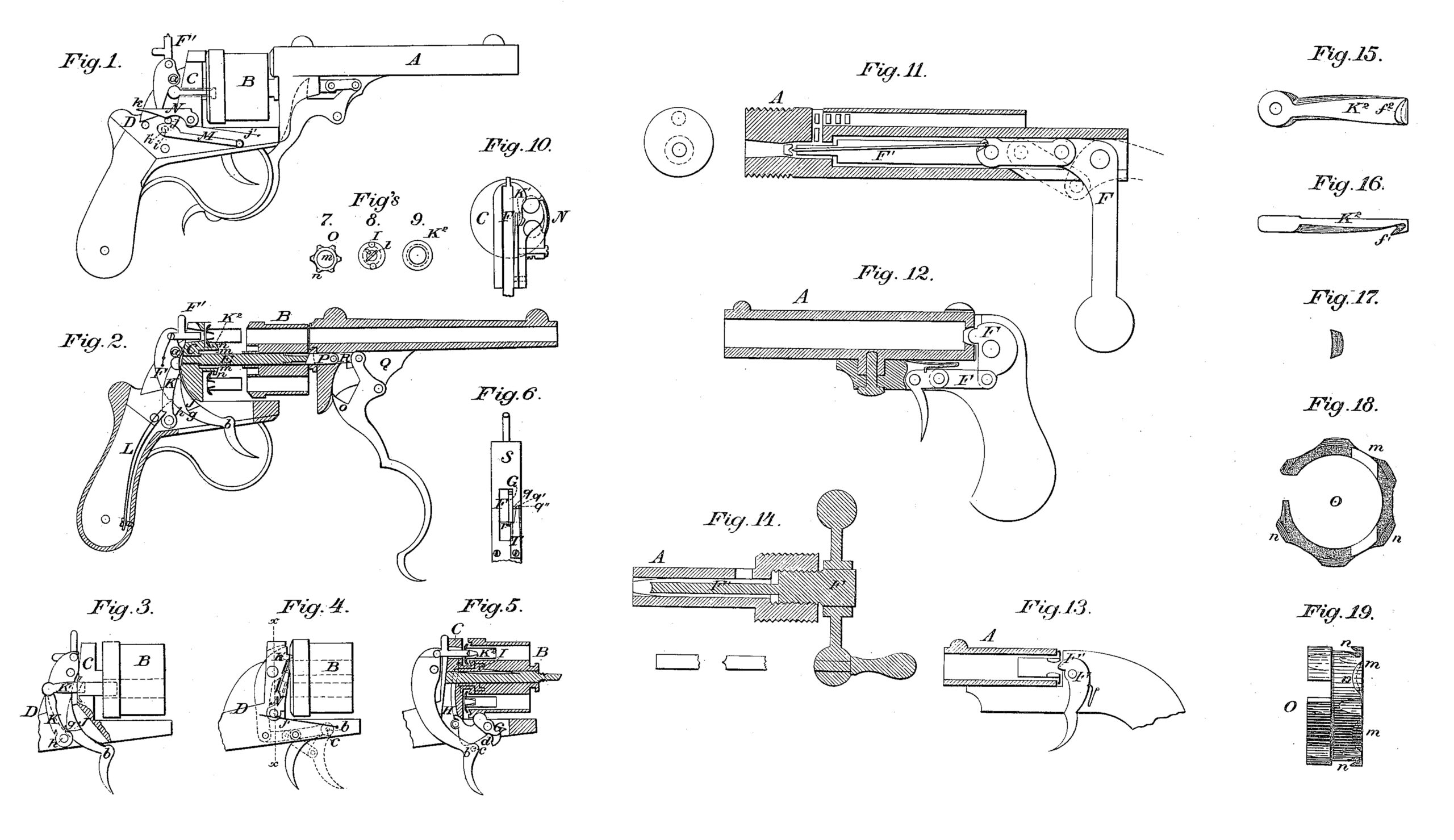
Figure 1 is a side elevation of a breech-loading revolving -chamber pistol with my improvement; Fig. 2, a vertical longitudinal action, of the same with the cylinder drawn rearward; Fig. 3, a separate view of the cylinder, recoil-shield, and the lock-frame, the latter being partly in vertical section; Fig. 4, a separate side elevation of Fig. 3; Fig. 5, a separate vertical longitudinal section of the me figure; Fig. 6, a detached view of the under side of the lock-frame. Fig. 7 represents the front of the cartridge-extractor which extracts all the cartridges at once; Fig. 8 the front end of the ratchet by which the cylinder is rotated; Fig. 9, a modification of Fig. 7. Fig. 10 is a cross-section on line x x in Fig. 4; Fig. 11, a separate view of firing mechanism as adapted to a cannon; Figs. 12 and 13, separate views of the same adapted to non-cylinder fire-arms, and Fig.14 the firing mechanism adapted to be used with a crew; Fig. 15, a separate view of the single cartridge extractor, with the hook to the front; Fig. 16, a side elevation of the same; Fig. 17 a separate view, showing the construction of the front of the point of the hook; Fig. 18, a front presentation of the cartridge-extractor for extracting all the cartridges at once; and Fig.19 a side elevation of the same.
In the drawings, A represents the discharging-barrel; B, the cylinder; C, the recoil-shield; D, the lock-frame, and E the base-pin, on which the cylinder rotates.
The firing mechanism is composed of a lever, F, which is pivoted at a, and at its upper end has pivoted to it a plunger, F’, passing through a suitable opening in the recoil-shield, in a line with the chamber of the pistol which is intended to be discharged. It is evident, however, that instead of having the plunger F’ pivoted to the lever F, it may be a rigid projection of the same.
In the operation of this plunger the discharge of the cartridge is due to the pressure upon the portion of the same which is charged with fulminating-powder, instead of by percussion of the same; and to forward this mode of action I have invented certain cartridges, which are subject of a pending application for Letters Patent of the United States.
Modifications of this firing mechanism are shown in Fig. 11, where it is applicable to cannon, and in Figs, 12 and 13, where it is applicable to non-chambered pistols and other similar fire-arms, and in Fig. 14, where it is operated with a screw instead of a lever.
Connected with this firing mechanism is that for rotating the cylinder, which is constructed as follows: A pin or projection, b, secured to the lever F at the point c, upon being moved forward by the forward movement of the lever or trigger part of the lever F, strikes against the lower part of the pivoted cam G, and passes into the curved recess d, and withdraws the upper part of said cam from a recess in the cylinder, and leaves the same free to revolve. By the same movement of the cam a pawl, H, which is pivoted to one end of it at the point e, is drawn down the distance of one notch in the ratchet I, by the revolution of which the cylinder is rotated. When the trigger is drawn back the pin b presses against the resisting side of the recess d, and revolves the cam G partially, thus raising the pawl end of the same, which pawl, engaging with a notch of the ratchet, revolves the cylinder a sufficient distance to bring one chamber of the cylinder in line with the discharging-barrel. When the cam is rotated a sufficient distance for the purpose named, it has been raised to such a point that the pin b is released from its recess d, and the locking portion of the cam G returns to its recess in the cylinder, locking the same against further rotation.
Connected, also, with this rotating mechanism is the mechanism for extracting the cartridge, which is constructed and arranged as follows: Upon the front side of the lever F is a projection, J, of the form shown in Figs. 2 and 3. When the lever F is drawn back the curved face of this projection strikes against the curved side of the pivoted arm K, to the upper end of which is pivoted the extractor-arm K1, having a proper hook or head, K2, and moves backward the arm K, which, in turn, draws back the extractor-arm and its hook. By the curved construction of the sides of the projection and the side of the pivoted arm K, against which it strikes, there results at first a slow motion of the extractor-hook in detaching the cartridge from its chamber, and then a more rapid motion of the same, resulting in sudden stop of the same, when the bottom g of the projection comes into the notch h of the arm K1, which sudden stop throws off the cartridge from the extractor-hook. A spring, L, pressing against the arm K1, throws the extractor-head forward to its work. A spring M, having a pin, h’, is placed upon the outside of the lock-frame. When the extractor mechanism is in use the pin h’ may rest in the hole i, where it touches no part of the mechanism.
When it is desired to use the pistol without the operation of the extractor, the pin h is placed in the hole j, when it comes in front of the arm K, the same being first drawn back, is previously explained, and locks the same in that position.
It is evident, however, that the cartridge-arm K1 may be pivoted directly to the lever F, or be a projection of the same.
In case certain cartridges are used, where it is intended to preserve the base, the body of the case to be discharged with the ball, it will be found convenient to lock back the arm K1, as before described, and use the following convenient mechanism for extracting such cartridge-bases: An extractor, N, of the form shown in Figs. 1 and 4, is pivoted upon the outside of the lock-frame, and is held up to its work by a spring, j’. When this extractor is in position its front side rests against the rear end of the cylinder, with its pointed upper end k extending by the side of the opening of one of the chambers. When the cylinder is rotated after firing, the point k comes under the flange of the cartridge, and as the cylinder is further rotated the cartridge-base is carried along the wedge shaped upper end of the ejector until it is wholly ejected from the chamber, as shown in Fig. 4.
When the use of this ejector is not desired, it can be turned down out of the way, as shown in Fig. 1, and it will be held in such position by the spring j’.
As before described, the mechanism is adapted to extract one cartridge at a time; but, when desired, all the cartridges may be extracted at the same time by the following mechanism: An extractor, O, has a body, which enters the recoil-shield, and is prevented from turning by a pin, l, has its head m shown in Fig. 7, with hooks n, as shown in Fig. 2, extending into the rear end of the cylinder, and fitting into a groove therein, so that when the cylinder is rotated the rim of the extractor-lead, carrying the hooks, would traverse in such groove. This head is shown particularly in Figs. 18 and 19, and its hooks n have each the form of those described in Figs. 15 and 16. This head extends such a distance into such cylinder as not to interfere with the mechanism before described for extracting one cartridge at a time. It is apparent, then, that if the cylinder is moved forward on its base-pin, all the cartridges will be held by the hooks under each one, and will be extracted.
As, however, it is difficult to start the cylinder in drawing it out against the resistance of the cartridges, I use a tube, P, upon the rear end of which a screw-thread is cut, which engages with a corresponding screw-thread upon the base-pin, and is screwed thereon. If, then, the barrel of the pistol is turned a little, the screw-thread mentioned will create a leverage, and draw out the cylinder a little on the base-pin, which will start the cartridges, and then the cylinder may be moved out in the usual way, or drawn entirely off.
This tube P is pivoted to the upper end of the lever Q by means of a pivoted connection, R. The ever has also a fin, o, adapted to fit into a corresponding recess in the under side of the barrel projection, and into a recess in the tube.
When the lever Q is moved forward the fin is withdrawn out of its recess, and the barrel may be turned, as described, and barrel and cylinder removed. The barrel, however, may be turned without withdrawing the fin whenever the free end of the lever is disengaged from the lock-frame. When the lever is drawn back the fin o enters its recesses, and the barrel and cylinder are both locked, the barrel prevented from turning, and the cylinder from moving forward. It is apparent, however, that the lever Q and its connection R, may be dispensed with, and the tube be rigidly secured to the under side of the barrel, and any convenient or proper mode of locking both the barrel and the cylinder be adopted. It is also evident that the screw upon the end of the base-pin may be dispensed with, and the end of the base-pin be beveled, to agree respondingly-beveled stop in the tube, against which the end of the base-pin rests, so that with a cor by turning the tube the action of the two bevels would separate the end of the base-pin from such stop. As, however, in withdrawing the cylinder, as above described, the extractor might be withdrawn with the cylinder, I prevent this result by a leaf-spring, p, upon the base-pin, the free end of which spring rests against the front end of the ratchet, the flange of which prevents the extractor from moving forward with the forward movement of the cylinder, so that when the cylinder is withdrawn the ratchet remains behind.
It may be desirable to provide against untimely discharges of the pistol, and for that purpose I usa a contrivance shown in Fig. 6, which represents the guard-frame of the under side of the lock-frame. Through this plate (shown at S) the trigger portion of the lever passes, and also a portion of the cam. Upon this plate is pivoted the spring T, with its free ends rounded and curved to fit into the holes q q1 q2. This spring has a shoulder, r, upon one side. When the point of this spring enter the hole q, then the lever is locked forward, because the shoulder r comes behind the trigger portion of the lever.
In commencing to discharge a pistol where all the chambers are loaded, it is desirable that the extractor should not operate at the discharge of the first chamber, because, if it did so, it would eject a loaded cartridge. I therefore draw back the extractor and pull back the trigger far enough to revolve the cylinder one notch, and then press the point of the spring into the hole q1. The cartridge head or hook of the cartridge-extractor then will rest against the rear of the cartridge, and will not operate to extract it, and the trigger may be moved back for a discharge, but cannot be moved forward. This result is accomplished. by the shoulder r, entering a proper recess in the cam. The pistol may then be discharged, and, in turn, all the discharged cartridges will be ejected in the act of firing.
When the point of the spring r is placed in the hole q2, which does not touch any of the mechanism of the lock-frame, the pistol can be operated and discharged in the usual way.
Having thus described my improvement, what I claim as new therein is–
1. In a fire-arm or piece of ordinance, a firing mechanism consisting of a lever and a plunger or firing-pin attached to the same, and adapted to operate by pressure alone, substantially as described.
2. In a cylinder fire-arm, in combination with the firing-lever, the pivoted cam and the pawl, substantially as described, for revolving the cylinder and discharging the fire-arm at the same time.
3. The cartridge-extractor, with hook shaped head and round point, substantially as described.
4. The cartridge-extractor K2, in combination with the lever for firing, each constructed and arranged substantially as described.
5. The wedge-shaped pivoted extractor N, constructed and arranged to operate substantially as described.
6. In combination with the base-pin, the tube P, substantially as and for the purposes set forth.
7. In combination, the spring T and lever F, substantially as and for the purposes set forth.
8. The fin o on the lever Q, in combination with a recess in the tube or base-in, to fasten it to the barrel, substantially as set forth.
9. The spring L, in combination with the extractor K K1, substantially as set forth.
10.The spring p in the base-pin, in combination with the extractor, substantially as described.
In testimony that I claim the foregoing I have hereunto set my hand this 8th day of April, 1876
Rollin White
Witnesses:
H. R. White,
H. W. Bailey.