
USA 707
UNITED STATES PATENT OFFICE.
RUFUS NICHOLS AND EDWARD CHILDS, OF CONWAY, MASSACHUSETTS.
IMPROVEMENT IN MANY-CHAMBERED-CYLINDER FIRE-ARMS,
Specification forming part of Letters Patent No. 20, dated April 24, 1838.
To all whom it may concern:
Be it known that we, Rufus Nichols and Edward Childs, of Conway, in the county of Franklin and Commonwealth of Massachusetts, machinists, have invented, made, and applied to use a new and useful Improvement in the Construction of Fire-Arms, and which, to the best of our knowledge and belief, has not been heretofore known, used, or employed; and we do declare the following specification, together with the drawings hereto annexed and referred to, to be a full and exact description of our said machine and invention, viz:
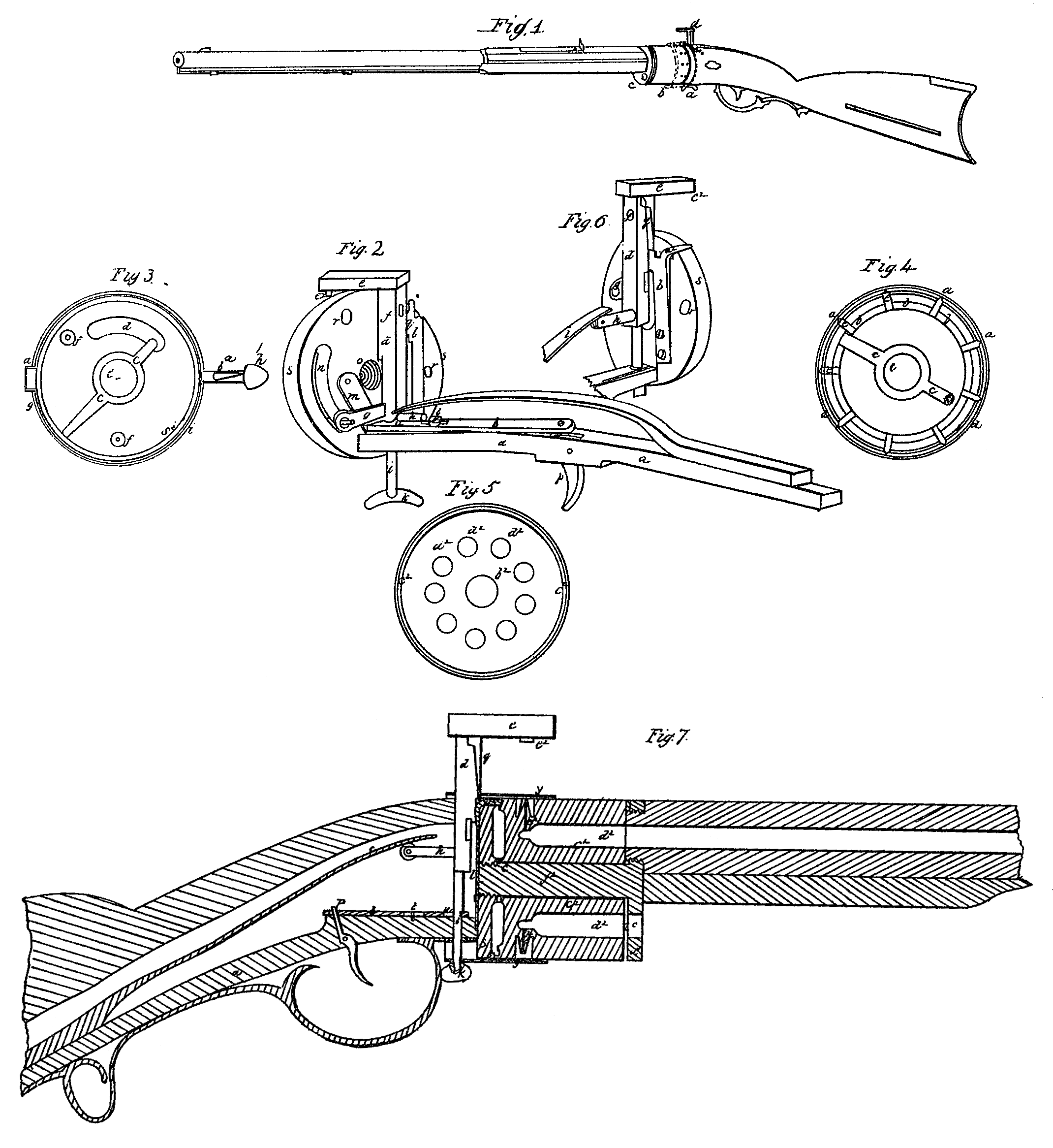
The lock is constructed as follows: The bedplate, through which the trigger passes and on which the guard is affixed, is a firm metallic which the guard is affixed, is a firm metallic plate passing from behind the guard forward, and is affixed to a circular plate on the end of the stock. The upper end of the trigger P, Figures 2 and 7, passes through the end of a metallic bar, b, lying on the bed-plate a, and which bar is held in its place by a screw, c, passing through a mortise in its center perpendicularly into the bed-plate. In the extreme end of this bar is a perpendicular aperture, u, through which the hammer-rod hereinafter mentioned is inserted.
The hammer or cock consists of a perpendicular rod, d, passing through the bed-plate a, near its junction with the circular plate s on the end of the stock, and through the aperture on the end of the horizontal barb, attached to the trigger and upward through the stock. On its lower end is a thumb-piece, k, in the form of a segment of a circle, for raising it up with the hand. On its upper end is a piece or hammer, e, projecting, forward over the chamber-cylinder hereinafter described, at a right angle with the rod. Just below this upper horizontal piece, and on the right side of the rod, is affixed a cam, I, to move against the forked spring hereinafter mentioned. Against the cam is an aperture, f, through the rod for a sight-hole. Above.the center of the hammer-rod is at arm, g, projecting horizontally from it to the left, and having a horizontal aperture through its extreme end opposite the slot in the circular plate on the end of the stock. Just below this arm on the rod is another, h, projecting from it to the rear, or toward the breech of the musket or pistol. On the front side of the hammer-rod and below the last-mentioned arm is cut a notch or shoulder, i, which, when e piece is cocked, rests on the front outer edge of the aperture in the front end of the horizontal bar before mentioned. Back of the trigger and on the upper side of the bed-plate is a strong spring, c, projecting forward and pressing upon that arm on the hammer-rod, h, which projects to the rear toward the breech of the piece. On the circular plate and to the right of the horizontal bar is screwed a spring, which passes perpendicularly upward near the periphery of the plate where it is forked, one tine, a^2, Figs. 6 and 7, being bent at a right angle and passing forward in a groove cut in the periphery of the circular plate, and the other shorter and standing upright to receive the calm on the hammer-rod, which being in the form of a wedge forces back in descending the time a^2, and consequently frees, it from the groove or notch e, Fig. 4, and allows the chamber-cylinder to turn. On the left side of this hammer-rod is affixed to the circular plate a spring, m, Fig. 2, passing diagonally downward against the end of the horizontal barb, to hold it against the notch i or shoulder cut in the hammer-rod, when the piece is cocked. The circular plate s s, before mentioned, is of metal, and to be strongly affixed to the end of the bed-plate and to the end of the stock by screws, welding, or otherwise. Through the center of this plate is a large female screw, o, Fig. 2, into which a corresponding male screw on the end of the barrel hereinafter mentioned is to be inserted. The outer or foreside of this plate is to be hollowed or scalloped, leaving a strong rim, s^2, Figs. 3 and 7, at the periphery.
Between the circular plate and the chamber-cylinder, hereinafter mentioned, is a short lever or needle, c, Figs. 3, 4, and 7, which, having a collar on its center, turns on the screw passing into the circular plate, and having two arms on its opposite sides, one of them moving in wedges or inclined planes b b, formed on a rim at the end of the chamber-cylinder, and thus turning it, Fig. 4, and the other arm extending to a slot or aperture in the form of a segment of a circle, as shown at d in Fig. 3, on the left side of the center of the plate, where this arm of the needle is bent at a right angle and passes through the slot and through the aperture in the extreme end of the horizontal arm g in Fig. 2 on the hammer-rod opposite the last-mentioned aperture in the circular plate.
The chamber cylinder c^2 c^2, Figs. 5 and 7, is a solid piece of metal of any required length and diameter, being perforated through the center lengthwise to receive the large screw on the end of the barrel, as represented at b^2, and on which this cylinder turns as on an axle. In its outer or fore end, and parallel with its axis, are bored any required number of chambers, d^2 d^2 d^2, for depositing the charges, and at their bases are drilled small holes, as touchholes, e^2 e^2, Fig. 7, from the periphery inward. On the periphery of the rear end of this cylinder, next the circular plate before mentioned, are cut at regular distances grooves or notches, Fig. 4, e e e, corresponding with the number of chambers in the cylinder, into which notches the bent tine of the forked spring before mentioned drops, when the hammer-rod is raised as the cylinder turns, and thereby placing and securing each chamber successively in a line with the bore of the barrel when it is discharged. On the rear end of this cylinder is turned a heavy rim, by which it is fitted close to the circular plate on the end of the stock. Within this rim is another a little depressed, and which is divided and formed into as many wedges or inclined planes as there are chambers in the cylinders. The longest end of the needle or lever c, beforementioned, between the circular plate and the chamber cylinder traversing on the wedges or inclined planes aforesaid, and being moved round by the connection of the other end of the needle with the hammer-rod as it lifts off from the inclined plane on turning back the cylinder, revolves and brings another chamber in a line with the bore of the barrel. On the rear of the butt-end of the barrel, and at right angles with the barrel, is a circular plate, d^3, Figs. 1 and 7, corresponding with the diameter of the chamber-cylinder, through which plate the barrel passes until it comes in close contact with the chamber-cylinder, passing over the space z, Fig. 7, allowed for the escape of an accidental discharge, and having an aperture, c, through it into the bore, and of the same size as the bore of the barrel. This plate is of sufficient distance from the chambers to allow for the escape of an accidental discharge of any of the chambers without danger to the person holding the piece, it being of sufficient strength to detain the ball within the chamber. This aperture c is within the center of the plate, and there is on the opposite side of and equidistant from the center another aperture of the same size. Through the center of this plate, or affixed in it, is a strong and firm screw, b^2, Fig. 7, which passes through the center of the chamber-cylinder, through the collar of the needle, and into the circular plate g on the end of the stock, where it is screwed as close as can be and permit the chamber-cylinder to revolve freely on it as an axis. The upper cross-piece on the hammer-rod may be fitted with a projection, e^2, for caps, pills, or any other kind of priming. To protect the percussion-caps from exposure to the weather, and as a shield or guard from blows and from dropping off, we place a ferrule or rim of metal, as represented by the red lines in Fig. 1, and by y y, Fig. 7, of a suitable width over the hind part of the chamber-cylinder, that can be drawn back far enough to adjust the caps, having notches in the front upper and rear lower edge to receive the hammer-rod.
The stock is similar to the common half-stock of a rifle or pistol, with a guard and trigger of the usual form underneath.
For a more clear and full description of our said invention reference is here had to the plans and drawings which are hereto annexed, and which are and are to be a part of this specification and description thereof.
Modus operandi: The several parts being put together, the piece is charged by bringing the chambers severally and successively to a line with the lower aperture, c, Fig. 1, in the plate d, to which the barrel is affixed. After this is done the operator places his finger upon the thumb-piece k, at the lower end of the hammer-rod, and pushes it up against the stock, when the diagonal spring on the back side of the rear circular plate forces the end of the horizontal barb, Figs. 2 and 7, under the notch or shoulder i in the hammer-rod, and the piece stands cocked. By the same movement the long end of the needle, which rested at the base of one of the wedges or inclined planes, presses against it and causes the chamber-cylinder to revolve on its axis the exact distance between two chambers, and brings necessarily a new chamber in a line with the bore of the barrel, and by the same operation the cam g is removed from behind the forked spring, and the bent tine of this spring falls into one of the notches on the end of the chamber-cylinder and confines it in its place. By pulling the trigger the end of the horizontal bar is removed from under the notch or shoulder on the hammer-rod, and the long spring on the end of the bed-plate forces the rod down and causes the caps or other priming to explode and the chamber connected with it to be discharged through the bore of the barrel. By this movement the cam falls back between the plate and the forked spring, and withdraws the bent time of this spring from the notch in the chamber-cylinder; and also by this movement the short arm of the needle passes over one inclined plane on the end of the chamber-cylinder, and is laid at its base.
What we claim as our invention, and desire to secure by Letters Patent, is—
1. The particular construction of the lock, as herein described, with the hammer sliding vertically, combined with the respective parts by which it is operated and upon which it operates, substantially as set forth.
2. The mode of constructing and combining the needle or lever so as, in conjunction with its appendages, as herein described, the revolving of the chamber-cylinder and the affixing it in its proper position are effected.
3. The ferrule or guard that surrounds the lower end of the chamber-cylinder, protecting the percussion-caps from exposure to the weather and from slipping off from the nipple, as herein described.
RUFUS NICHOLS,
EDWARD CHILDS.
Witnesses:
Otis Childs,
Wm, Billings.