
US 36984
UNITED STATES PATENT OFFICE.
S. W. WOOD, OF CORNWALL, NEW YORK.
IMPROVEMENT IN REVOLVING FIRE-ARMS.
Specification forming part of Letters Patent No. 36,954, dated November 18, 1862.
To all whom it may concern:
Be it known that I, S. W. Wood, of Cornwall, county of Orange, and State of New York, have invented new and useful Improvements in Revolving Fire-Arms, of which the following is a full, clear, and exact description, reference being had to the annexed drawings, in making part of this specification.
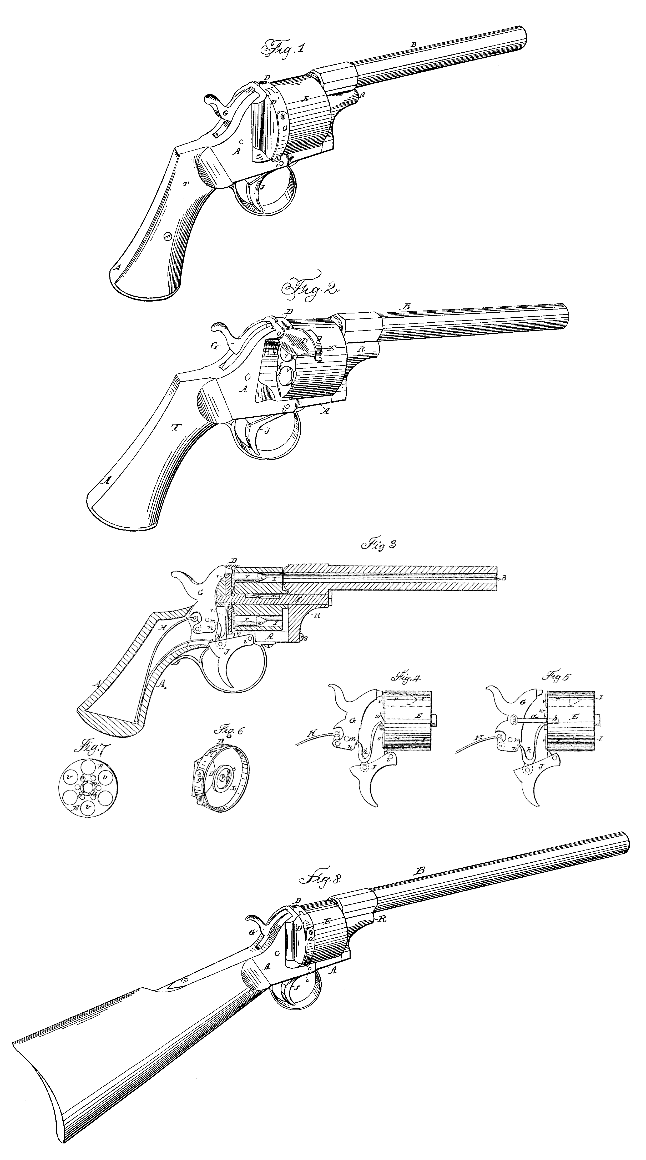
Figure 1 represents a view in perspective of a revolving pistol having my improvements applied thereto. Fig. 2 is a perspective view of a pistol like Fig. 1 with the hinged gate open, showing the manner of inserting the cartridges into the chambers in the cylinders and withdrawing the empty cases, also showing the inclined plane for starting the empty cases from the chambers. Fig. 3 is a vertical longitudinal section of figs. 1 and 2, representing the interior mechanism for operating the hammer to discharge the cartridges and for revolving the cylinder, also showing the cartridges in position. Fig. 4 is a detached view of the hammer, cylinder, trigger, and forked lever in a single piece attached to the trigger for operating the hammer and cylinder simultaneously in dis charging the aim. Fig. 5 is also a detached view of the hammer, cylinder, trigger, and forked lever in a different position, the hammer being raised slightly to allow the cylinder to turn freely to insert the cartridge and to withdraw the empty cases from the chambers after tile discharge, also showing a sliding bolt attached to and operated by the hammer to bolt the cylinder ill proper position while being discharged and to prevent the throwing off of the cylinder while operating rapidly, the recess to receive the bolt being shown in dotted lines. Fig. 6 is a perspective view of the hollowed or cupped breech for receiving and inclosing the rear end of the rotating cylinder and it casing the heads of the cartridges to prevent accidents by premature explosion, and through which the cartridges are inserted by means of a hinged gate. Fig. 7 is a face view of the cylinder detached with the cartridge in position, showing the series of recesses to receive the bolt corresponding in number with the clambers, also showing the ratchet by which the cylinder is rotated. Fig. 8 is a perspective view of a carbine having my improvements applied thereto, the changes being only in the stock and barrel.
The nature of my invention consists in hollowing or cupping a stationary or fixed breech, secured to or forming part of the frame or stock of a pistol, into which the rear end of a revolving cylinder is received, and incasing the heads of the cartridges, and fitted with a stationary inclined plane on its inner or front face to relieve the empty cases from the chambers, and so constructed that when the cylinder revolves with the gate closed the cartridges will pass over the inclined plane secured to the face of the hollowed breech and again be forced to their places in the chambers when in position to be discharged; also, in operating the hammer and revolving the cylinder by means of a forked spring-pawl in one piece pivoted to and operated by the trigger, one of the forks or longs serving as a spring to allow its end to pass over the notches on the end of the cylinder in revolving it, to present the chambers in succession to the barrel and to permit the other end taking into the notches in the face of the hammer to be forced thereform in discharging the piece; also, in the arrangement and combination of a revolving cylinder forked spring-pawl in one piece and safety-bolt pivoted to and operated directly the hammer, the whole actuated in harmony by the trigger, so that when the spring end of the pawl has revolved the cylinder and presented a chamber to the barrel the opposite end of the pawl is cast from the notch in the hammer and the safety-bolt, being carried forward with it, enters a corresponding recess in the cylinder and secures it in position.
Like letters indicate similar parts in all the figures.
To enable others skilled in the art to make and use my improved revolving fire-arm, I will proceed to describe the same in detail.
A in the annexed drawings represents the stock or frame of the pistol, upon which are mounted and arranged the various operating parts, and to the front end of which is secured the barrel B. To the front face of this stock is fitted a breech-piece, D, the face of which is hollowed or cupped out, so as to receive and incase the rear end of the revolving cylinder E and to incase the leads of the cartridges v. Around the center and upon its face is formed a rim, e, which receives the ratchet w of the cylinder E within it and prevents longitudinal or sliding motion of the cylinder and permits the cartridges to move freely in the face x of the breech. To the side of this breech is fitted a hinged gate, D’, which is closed by a spring o, through which the cartridges are inserted into the chambers and the empty cases withdrawn. (See Fig. 2.) This breech-piece may form part of the stock A, if preferred, or be fitted thereto, as represented. The barrel B has a shank,R, projecting from its lower rear end, through which a screw, S, passes to secure it to the front end of the stock A, and through the center of this shank R a pin, F, passes, which serves as a journal for the cylinder E to turn upon, and which extends through the breech-piece ID and into the stock A, securing the barrel and cylinder firmly in position with the rear end of the cylinder and heads of cartridges incased in the hollow breech.
To turn the cylinder E so as to present the cartridges r successively in position to be discharged by a blow from the hammer, and to impart positive and simultaneous motion to both hammer and cylinder, a forked spring-pawl, h, in a single piece, is arranged between the rear end of the cylinder E and face of the hammer G, (see Figs. 3, 4, and 5,) one end of the forked spring-pawl h taking into the notches m, formed in the face of the hammer G and the other end of the fork operating in the ratchet u, formed upon the end of the cylinder E.
The lower end of the forked spring-pawl h is pivoted to a vibrating trigger, J, hinged at i, so that when pulled by the finger the forked spring-pawl h rises perpendicularly, turns the cylinder E to the required position, presenting a chamber and cartridge in direct line with the bore of the barrel B, and at the same instant the lower end, n, of the hammer bears against the rear prong of the forked spring-pawl h, forcing it from the notches m and allowing the hammer G to descend upon and explode the cartridge by means of a spring, H, the opposite end of which bears upon the trigger and acts as a scar-spring to return the trigger into position after the discharge and when released by the finger.
To stop the cylinder at the required instant, and to lock it in position so that the chamber shall be directly in line with the bore of the B, a bolt, a, is attached to the face of the hammer G, and when thrown forward by the descent of the hammer upon the cartridge enters corresponding openings or recesses, b, formed in the rear end of the cylinder E. The recesses, b correspond in number with the chambers I, and are arranged in the proper relative position to lock each chamber directly in line with the bore of the barrel B.
To release the discharged cases from the chambers of the revolving cylinder a stationary or fixed incline-plane, f, is secured to or forms a part of the hollowed breech D, so that when the gate D is opened and the muzzle of the pistol pointed upward, by revolving the cylinder either with the trigger or by the fingers, the discharged cases will be drawn from the chambers by passing over in succession this stationary inclined plane; and when the gate D’ is closed and the pistol being discharged the front face of the gate D’, directly in rear of the inclined plane f and a short distance of the face of the breech D, is beveled or cut away to allow sufficient room for the heads of the cartridges to pass over the incline f, and when presented to the barrel to be exploded will again be forced into their proper position in the chambers.
Having thus fully described my improved revolving fire-arm, what I claim therein as new, and desire to secure by Letters Patent, is—
1. Hollowing or cupping the stationary or fixed breech secured to or forming part of the frame or stock of a revolving pistol and receiving and incasing the end of the cylinder and heads of the cartridges having a fixed or stationary inclined plane, the whole arranged and constructed as herein described.
2. In a self-cocking and discharging pistol, revolving the cylinder and operating the hammer by means of a forked spring-pawl in one piece, arranged as set forth.
S. W. WOOD.
Witnesses:
J. B. Woodruff,
W. G. Cranch.