
US 297801
UNITED STATES PATENT OFFICE.
SAMUEL S. HOPKINS, OF NORWICH, CONNECTICUT.
REVOLVER.
SPECIFICATION forming part of Letters Patent No. 297,801, dated April 29, 1884.
Application filed February 4, 1884. (No model.)
To all whom it may concern:
Beit known that I, Samuel S. Hopkins, of the city of Norwich, county of New London, and State of Connecticut, have invented certain new and useful Improvements in Revolving Fire-Arms, which improvements are fully set forth and described in the following specification, reference being had to the accompanying drawings.
My invention relates particularly to an attachment for revolving arms, by means of which the empty cartridge -shells may be expelled from the cylinder after firing, my object being to improve the efficiency of the arm without adding materially to its cost.
In most of the so-called “cheap grade of revolvers” there is no means provided for ejecting the empty cartridge-shells, the common method being to withdraw the axial pin of the cylinder, and, having removed the cylinder from the frame, to punch out the shells with said axial pin. Having thus removed the shells, the cylinder and pin are returned to their respective places in the frame, and the cylinder is again filled with loaded shells. Such a method causes an unnecessary waste of time, and frequently the loss of one of the detached parts.
In this invention it is my purpose to combine a convenient form of shell-ejector with the usual form of axial pin, the whole being so arranged that it may be used without removing the cylinder; yet, when so desired, it and the cylinder may be removed from the frame without the use of a screw-driver or other tools.
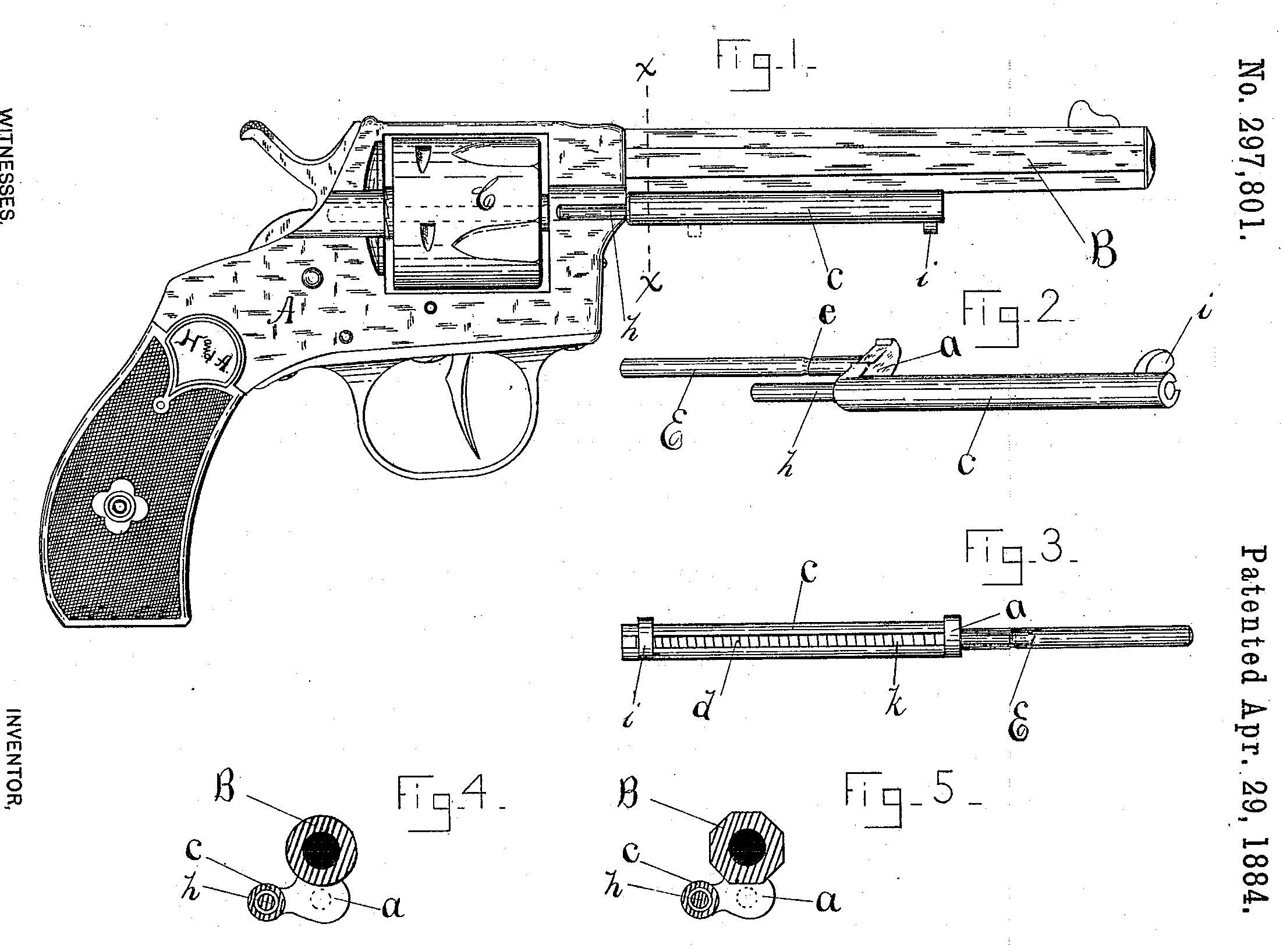
In the accompanying drawings, Figure 1. represents a revolver containing my improved ejector. Fig. 2 is a detached perspective view of said ejecting device. Fig. 3 is a view of the same from the rear side, as shown in Fig. 1, exposing to view the retractor-spring. Fig. 5 is a transverse sectional view on line x x, Fig. 1, illustrating the means which I employ to prevent the extractor-tube from swinging out of its proper position. Fig. 4 is a similar view showing the device applied to a revolver having a round barrel.
A represents the frame, B the barrel, and C the cylinder, of a revolver, all being of the usual form. That portion of the pin E which extends rearward into the frame, and on which the cylinder rotates, is also of the common form— that is to say, it is made of a section of round wire, and has an annular groove, e, into which a thumb-latch or friction-stud may enter to lock said pin in its place in the frame. Any of the several thumb-latches in common use may be used to retain my combined axial pin and ejector in place.
At or near the forward end of the frame is a laterally-extending arm, a, supporting a tube, c, which, when in place, is in alignment with one of the chambers of the cylinder C. In this tube c is a lively spiral spring, d, and within said spring is the ejector proper, consisting of a rod or wire, h, having a thumbpiece or handle, i, located immediately under the barrel of the arm, and which, when in use, travels in a longitudinal channel, k, in tube c. The upper side of the arm a, which connects the axial pin and ejector-tube, is so constructed that it conforms in shape to the barrel of the arm to prevent said tube from swinging out of its normal position. (See Figs. 4 and 5.) This method of Supporting the ejector in a given position forms a part of my invention.
To operate my device, bring the hammer to “half-cock,” when the cylinder may be freely rotated on its axis. Now, by forcing the thumb-piece i rearward, the ejector-rod is made to enter One of the chambers of the cylinder, and as it passes through said chamber (as indicated by dotted lines in Fig. 1) it forces the empty shell out before it. The spiral spring d, by its expansive force, now carries the ejector-rod forward, and the operation is repeated until the empty shells are removed, the cylinder being rotated by hand to bring the desired chamber into line with the ejector.
I am aware that an ejector-rod working in a tube fixed rigidly to the barrel or frame of an arm, and held forward in said tube by a spiral spring, is not new, and do not therefore broadly claim such a device; but I am not aware of an ejector-rod within a tube formed as a rigid part of the removable axial pin; and
I therefore claim as new and wish to secure by Letters Patent—
In combination with a revolver frame and cylinder, a removable axial pin having secured to its outer end, or formed as an integral part thereof, a tube, containing a spring-pressed ejector-rod whose forward end has a flange by means of which said rod may be forced rearward, the tube and ejector-rod being (when in place) in longitudinal alignment with the chambers of the cylinder, all arranged substantially as and for the purpose specified.
SAMUEL S. HOPKINS.
Witnesses:
John E. Warner,
Chas. H. Preston.