
US 195562
UNITED STATES PATENT OFFICE.
THOMAS W. BEARCOCK, OF PITTSTON, PENNSYLVANIA.
IMPROVEMENT IN REVOLVING FIRE-ARMS.
Specification forming part of Letters Patent No. 195,562, dated September 25, 1877; application filed August 4, 1877.
To all whom it may concern:
Be it known that I, THOMAS W. BEARCOCK, of Pittston, in the county of Luzerne and State of Pennsylvania, have invented certain new and useful Improvements, in Revolving Fire-Arms; and I do hereby declare that the following is a full, clear, and exact description thereof, which will enable others skilled in the art to which, it appertains to make and use the same, reference being had to the accompanying drawings, which form a part of this specification, and in which–
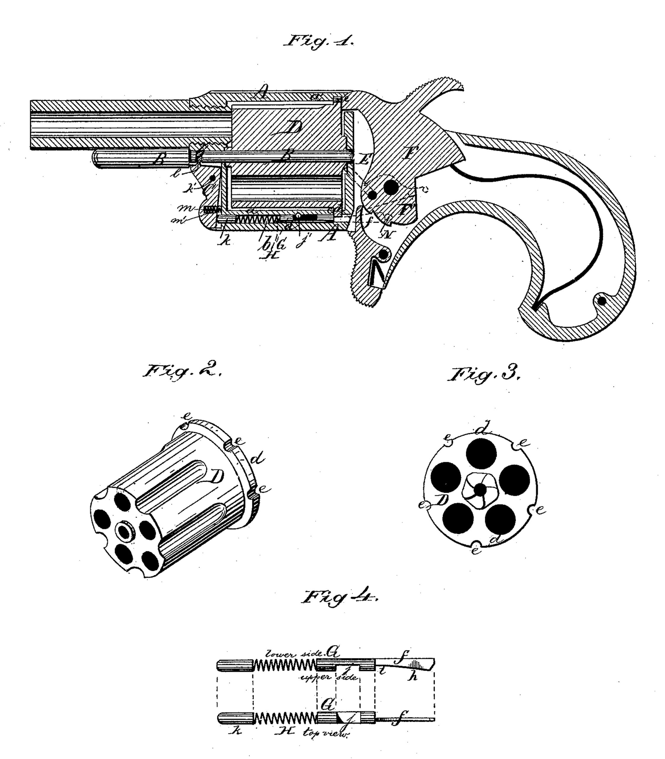
Figure.1 is a longitudinal vertical section of a revolver having my improvements. Fig. 2 is a perspective view of the cylinder detached. Fig. 3 is a rear elevation of the same. Fig. 4 is a side and top view of the locking-bolt detached, showing the various sections of which it is composed. Fig. 5 is a side view, partly in section, of the lower part of a revolver, showing the method of operating the locking-bolt. Fig. 6 is a similar view, showing the locking bolt and hammer in a different position. Fig. 7 is a perspective view of the catch detached.
Similar letters of reference indicate corresponding parts in all the figures.
This invention relates to locking devices for the cylinders of revolving fire-arms.
It consists, first, in providing the cylinder with a circumferential flange at one end there of; secondly, in disposing the notches with which the locking-bolt or other locking device engages, in this flange, instead of, as heretofore, in the body of the cylinder; thirdly, in the construction and arrangement of a locking-bolt peculiarly adapted to this form of cylinder, it being arranged to operate, for locking or unlocking the cylinder, with a single sliding motion, without a swing; and, fourthly, in the mechanism for operating the locking-bolt, all as and for the purposes which I shall now proceed more fully to describe.
Referring to the drawings hereto annexed, the letter A represents the metallic body or frame of a revolver having my improvements. B is the central pivot-pin, which passes longitudinally through the frame, where it is retained by the catch C, hereinafter described.
D is the cylinder. This has a circumferential flange, d, formed, preferably, upon its lower or butt end, as shown in the drawings. It may, however, be formed upon the upper end of the cylinder, or even at an intermediate point thereof, without changing the nature of my invention, the construction of the locking-bolt being in such case correspondingly modified.
The under-side piece a of frame A has a longitudinal perforation, b, for the reception of the locking-bolt G and the spring by which it is operated. The upper and lower side pieces a’ a of frame A both have grooves for the reception of the flange d of cylinder D, that in the lower side piece being cut through to the longitudinal perforation b, thus forming an opening or passage, c, through which the end of the locking-bolt projects, so as to engage with the notches e in the flange d of the cylinder.
The locking-bolt proper consists of a short slender metallic rod, having at its lower end a flat spring, f, which projects into the chamber E, in which the hammer F is pivoted, and rests flat upon the side of this latter.
The end of spring f is beveled or tapering, as shown at is and upon its inner side, as shown at h, in Fig. 4, which is an enlarged view, it has a minute triangular recess, made with a file, for the purposes hereinafter described.
In order to cause the spring f to lie flat upon the side of the tumbler without bending outward, it is disposed upon the side, and not upon the middle, of the end of the locking bolt, as shown in the top view indicated in Fig. 4. The lower part of the side of the hammer, upon which it rests, is also preferably cut away for this purpose, as shown at F. A recess, j, is formed in the upper side of the locking-bolt, so as to permit the insertion transversely through the lower side piece of frame A of a pin, j’, the object of which is to prevent the locking-bolt from turning round, which would prevent its successful operation.
In the perforation or recess b, above the locking-bolt, is placed a spring, H, above which I prefer to place a metallic rod, k, working against the catch C, as shown in the drawings. This latter, however, may be dispensed with, provided that the spring H is made long enough to work against the catch directly. The catch C is placed in a recess formed for its reception in the forward end of frame A, where it is held in place by a pivot-pin, k’. A tooth, l, formed upon catch C, engages with the circumferential groove b’ in pivot-pin B, which is thus retained in position. The catch C is operated partly by the action of spring H, which operates the locking-bolt; but in order not to depend wholly upon this for action, I provide the catch with an extra spring, m, placed in a recess, m’, in the under side thereof, and working against the bottom of the recess, in which it is pivoted.
The locking-bolt is operated so as to lock or unlock the cylinder by the action of the hammer in the following manner. Upon the side of the hammer, just behind the spring f of the locking-bolt, is formed a small beveled stud, N. When the hammer is raised to half-cock, as shown in dotted lines in Fig. 5, this stud engages with the rear beveled end of spring f, thus pushing the locking-bolt forward far enough to disengage it from the notch in flange d of the cylinder, which is thus permitted to revolve, actuated by revolving mechanism of any suitable approved construction.
When the hammer is raised to full-cock, as shown in Fig. 6, the stud N slides by the beveled end of spring f of the locking-bolt, which thus, impelled by spring H, slides back to its former position, where it engages with the next notch in flange d of the cylinder. The stud N is now above the spring f. When the piece is fired it passes under the spring f, which is thus momentarily forced outward until it occupies its former original position.
It is in order to enable this last operation to be performed without danger of breaking or injuring spring f that this latter is provided with the recess h, before mentioned. This enables the beveled side of stud N to slide freely under the spring without danger of catching. It should also be remarked that the spring f must have, just behind the body of the locking-bolt, a notch, or it must slant down toward this point, as illustrated in the drawings, in order not to interfere with the operation of the cylinder.
It is obvious that the locking-bolt may be operated by the action of the trigger instead of the hammer, without changing the nature of this part of my invention.
From the foregoing description, and by reference to the drawings hereto annexed, the operation of my invention and its advantages will be readily understood.
It is obvious that the principle herein shown for locking and unlocking the cylinder, provided with a flange, may be modified in a variety of ways, not only when this is made necessary by the formation of the flange upon the front end or at an intermediate point of the cylinder, instead of upon the butt-end thereof, but also when the flange, instead of notches, is provided with recesses or perforations, which would necessitate a corresponding modification in the construction of the locking bolt. The method of operating this latter would not, however, require to be changed.
Having thus described my invention, I claim and desire to secure by Letters Patent of the United States
1. In a revolving fire-arm, the combination of the cylinder, having a circumferential notched flange, with a locking-bolt operating with a single sliding motion to engage with recesses or notches in said flange, substantially as described, for the purpose shown and specified.
2. The locking-bolt G for revolving fire-arms, herein described, consisting of a metallic rod having recess j, and flat spring f having beveled end i and recess h, the upper edge of the spring slanting down toward the body of the bolt, substantially as described, for the purpose set forth.
3. The frame A, having a longitudinal perforation, b, in its under-side piece, in combination with the sliding locking-bolt G, herein described, and pin j’, substantially as described, for the purpose shown and specified.
4. The combination of the locking-bolt G, herein described, with the hammer F having beveled stud N, substantially as described, for the purpose set forth.
In testimony that I claim the foregoing as my own I have hereto affixed my signature in presence of two witnesses.
THOMAS W. BEARCOOK.
Witnesses:
CHARLES F. SQUIRES,
HENRY B. STALL.