
US 136134
UNITED STATES PATENT OFFICE.
WILLIAM CLEWS, OF ILION, NEW YORK.
IMPROVEMENT IN CARTRIDGE-RETRACTORS FOR REVOLVING FIRE-ARMS.
Specification forming part of Letters Patent No. 136,134, dated February 25, 1873.
To all whom it may concern:
Beit known that, William Clews, of Ilion, in the county of Herkimer and State of New York, have invented certain Improvements in Revolving Fire-Arms; and I do hereby declare that the following is a full and exact description thereof, reference being had to the accompanying drawing making part of this specification—
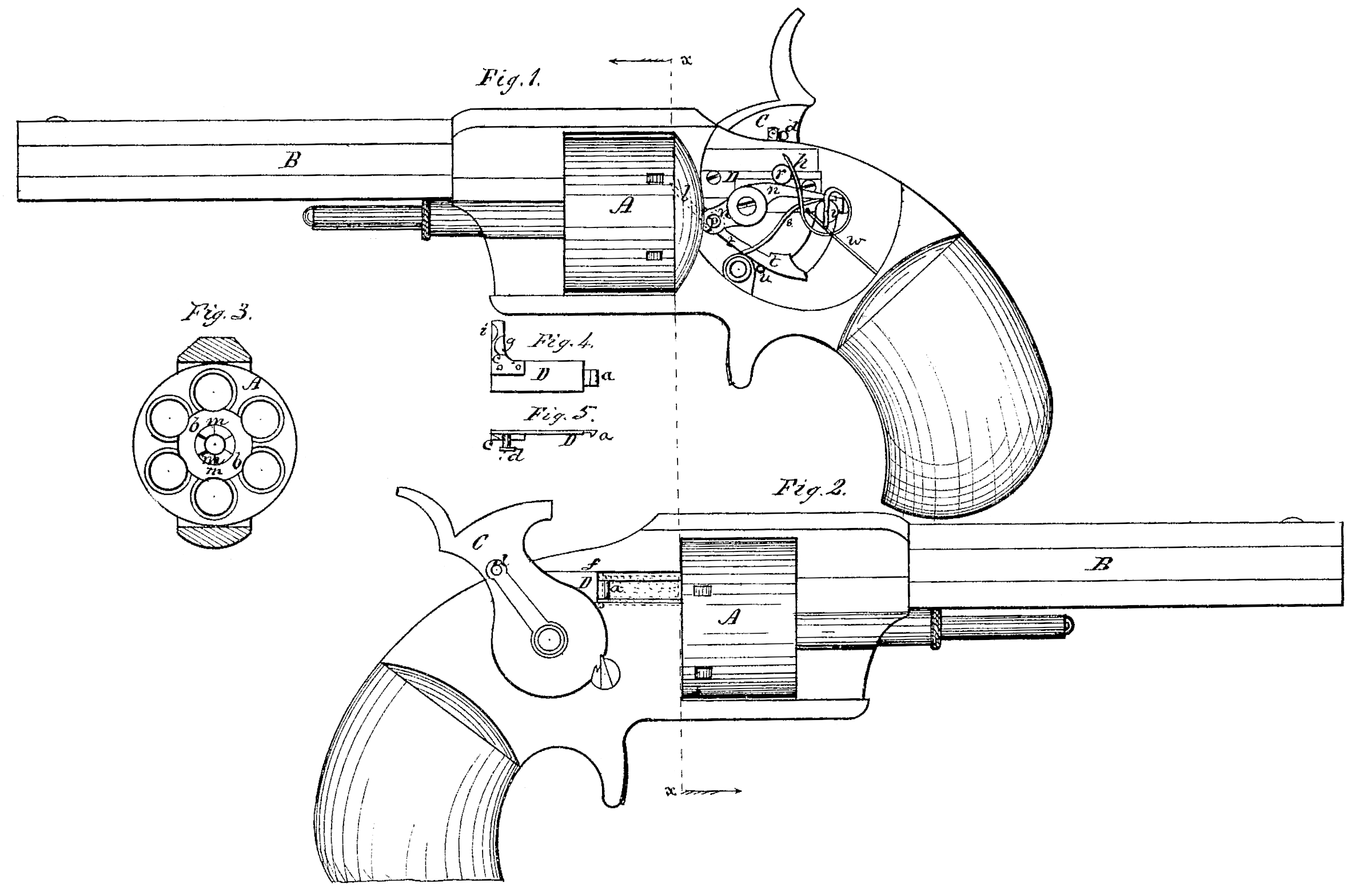
Figure 1 being a left-side view of a revolving-cylinder pistol provided with my improvements, showing the interior arrangement of the lock and its connections; Fig. 2, a right-side view of the same; Fig. 3, a transverse section thereof in a plane indicated by the line x x, Fig. 1; Figs. 4 and 5, views of parts detached.
Like letters designate corresponding parts in all of the figures.
The main feature of my invention consists in an improved cartridge-shell retractor, which automatically withdraws the shells of the cartridges as fast as exploded by the direct action of the hammer in cocking, the retractor being set free from the hammer and returning to position for tie next retraction when the hammer reaches half-cock; and another feat. tire consists in an improved means for turning the cylinder, so that it shall not bring the shell of the last-exploded cartridge in the line of the retractor fill the latter returns to position after withdrawing the previous shell.
In the drawing, let A represent the revolving cylinder of the fire-arm, B the barrel, and C the hammer. In order to properly locate the parts composing my invention and render their connection and operation convenient, I place the hammer at one side of the stock and bend it laterally, bringing the face or point thereof in line with the barrel B and the upper bore of the cylinder A. The retractor D consists of a sliding piece with a hook or catch, a, on the forward end to catch around the flange of the shell, so as to withdraw the same, which is done by a direct backward-sliding movement of the retractor. This catch projects radially outward from the axis of the cylinder, and the inner part b of the rear end of the cylinder is cut away so as to form a recess to receive the said catch, this recess also cutting into each bore of the cylinder, as shown, so that the catch may reach the flange of the cartridge-shell. The retractor is drawn back ward by the direct action of the hammer, with which it is coupled for the purpose, by means of a projection, c, on the retractor and a coup ling-pin, d, on the hammer. The coupling-pin d slides outward and inward in the hammer, and is pressed inward against a plate or surface, f, over which the projection c of the retractor slides. In the front edge of the projection c is an inclined surface, g, Fig. 4, so located that at or just before the moment when he hammer reaches half-cock the coupling-pin d, which bears against the front edge of the projection to draw the retractor back, will reach the said inclined surface by the circular movement of the hammer, and will slide over the projection and allow the retractor to be driven forward into position for withdrawing the next shell by means of a spring h, Fig. 1, or its equivalent. The hammer and retractor are so arranged in connection that the cartridge-shell is entirely withdrawn, so that it will fall from the pistol at or before the hammer reaches half-cock, leaving the retractor free to spring forward, as above specified. On the back edge of the projection c is another inclined surface, i, over which tie coupling-pin slides in the forward movement of the hammer at the discharge of the pistol, and thus regains position in front of the said projection, ready to draw back the retractor at the next lifting of the hammer. In order that the shell of the last-exploded cartridge may not be in the way of the retractor in regaining position for the next retraction the cylinder should not be turned, or fully turned to bring the succeeding cartridge into line with the barrel, till after the hammer passes half-cock. I effect this movement, and by means substantially as follows: In order to effect the final turning of the cylinder as quickly as possible just before the hammer reaches full-cock it is desirable to produce part— say one-half— of the turning movement as soon as the hammer reaches half-cock, and yet this cannot be done till after the retractor withdraws its shell each time I therefore produce the first partial turning of the cylinder by the forward movement of the retractor. The device shown in Fig.1 effects this purpose. The pawl l, which takes into the notches m m of the cylinder, is pivoted to one end of a cam-lever, n, at p. The other end of the lever is a cam-surface, which is pressed against a stud, r, projecting from the retractor, by a spring, s. This cam-surface is so shaped that as the retractor is withdrawn the stud r allows the forward end of the bar to draw back the pawl l to its lowest position for taking into the next notch m of the cylinder. Then, as the retractor springs forward, the stud r, bearing against the cam-surface of the lever, depresses that end, and thereby pushes the pawl l along, so as to partially turn the cylinder, as required. The remainder of the turning movement of the cylinder is produced by the hammer C just before it reaches full-cock. For this purpose I employ a sliding dog or cylinder-lifter, t, situated substantially as shown in Fig. 1. Its forward end is pivoted to the pawl l at the cam-lever pivot p, or otherwise, and it is by its forward-sliding action that the said pawl is caused to complete the turning movement of the cylinder. Its lower surface slides on a fixed stud, u, or the equivalent thereof, to keep it in position, and its rear end lies in the path of a projecting pin, v, of the hammer, so arranged that just before the hammer reaches full-cock this pin will strike the rear end of the dog and drive it forward far enough to complete the turning of the cylinder. This projecting pin v may serve for the mainspring w to bear against. The retractor D has or may have a projecting point on its forward end to enter recesses in the cylinder for locking the same in position.
Since with this automatic retractor the chambers of the cylinder are cleared of the empty shells as fast as the cartridges are exploded, the cylinders may be charged with cartridges, one by one, on the left side, while firing the revolver, by having the breech on that side cat away at one point to permit their insertion, and the entire cylinder is readily charged with cartridges all at once in this way.
What I claim as my invention, and desire to secure by Letters Patent, is—
1. The cartridge-shell retractor D, in combination with the hammer C, arranged substantially as described, so as to automatically disengage itself from the hammer and return to position during the lifting of the hammer, for the purpose specified.
2. The automatic cartridge-shell retractor D, drawn back by the hammer and arranges as herein described, so as to withdraw the cartridge-shell at or before the time the hammer reaches half-cock, and then be separated from the hammer, leaving the latter free in rising from half to full cock, substantially as herein specified.
3. The cartridge-shell retractor D, provided with the projection c having inclined surfaces g i, in combination with the spring coupling; pin or catch d in the hammer C, substantially as and for the purpose herein specified.
4. The combination of the cam-lever n, and its pawl l with the cartridge-shell retractor D, so that the said retractor, while springing for ward into position, moves the cylinder, substantially as and for the purpose herein specified.
5. The dog s, arranged substantially as described, or its equivalent, in combination with the hammer, and operating so that the turning movement of the cylinder is made or completed each time, by the hammer just before it reaches full-cock, substantially as and for the purpose herein specified.
Specification signed by me this 3d day of May, 1872.
WILLIAM CLEWS.
Witnesses:
Edm. F. Brown,
J. S. Brown.