
British 18294
We, The Webley and Scott Revolver and AbAis Comtany Limited of Weaman. Street- ‘Birmingham, Revolver Manufacturers, and William John Whiting, of Douglas Road, Handsworth. near Birmingham, Works Manager, do hereby declare the.”nature of this – invention to be as follows: —
This, invention has relation to quick-loader or charger attachments for the ammunition employed’ in connection with revolver-pistols and analogous maga-zin fire-arms, and has forits object> to provide; a simple and eheaply-produced clip or coupler adapted to hold together a series of cartridges in groups or clusters,’and to admit of a number of cartridges forming a complete charge to he loaded into the cylinder as quickly as a single cartridge, whereby the rapidity of firing is greatly increased.
The improved loader, as adapted for use in connection with revolver ammunition, comprises a thin disc of sheet steel or other metal, or any other suitable material, pierced with a circular ring of holes, corresponding in number and position to the chambers in the cylinder of the arm to be charged, whilst the diameter of the said holes is such that the cartridges to be coupled together shall fit. tightly therein on being forced through up to the heads, -which are of larger diameter than the holes. This attachment thus provides a means for coupling and holding together a number of cartridges. in their proper relative positions and to admit of the same being passed or dropped collectively into the cylinder of the revolver, with each cartridge lying respectively in its proper chamber. *
The coupling discs are made, of such thin material that, on the cartridges being passed fully home, into their chambers, the same lies close against the hack end of the cylinder and does not interfere with the closing of the revolver, when the disc comes between the cylinder and the standing breech. The disc is of about the same diameter as, or a little less than, that of the cylinder and may have a central piercing to. fit over a shoulder on the rearward end of. the extractor slide, although this is not material or essential.
When the revolver is opened the extractor slide acts against the loader disc and withdraws the spent cartridges through the medium of the said disc, instead of the ejector arms acting against the heads of the cartridges direct in the usual way. The disc and spent cases are thus ejected bodily and the disc is thrown away with the cases.
Instead of the holes in the loader disc or coupling frame being made a tight fit onto the cartridges, the latter may be made a loose fit, so as to admit of any one or more cartridges or spent cases being removed separately by hand.
AVe do not confine ourselves to the particular form of disc coupler above described as a loading coupler, may be made in the form of a ring with overhanging edges to overhang the rims or heads of cartridges which are slid into tlie said ring, the back of which has a series of holes corresponding .to the positions of the cartridges when in the chambers, and through which the striker of the revolver passes.
If necessary or desirable, the face of the standing breech, or the bach, of the cylinder of a revolver may be slightly, sunken to form a seating in which the coupling’ disc lies, and further) we wish it to be understood that we do not confine ourselves to ,any particular method of fixing or connecting the cartridges to the coupling plate or’ring, nor to the material from which the carrier is made-
Dated this 12th day of September 1901
THE WEBLEY >&’SCOTT REY0LYER& ARMS COMPANY . – -LIMITED, . » ‘
… WILLIAM JOHN WHITING
By Henry Skerrett’
Agent for Applicants.
COMPLETE SPECIFICATION.
f‘Improvements in Quick-loader or Charger Attachments for the Ammunition of Revolver and Magazine Fire-arms”.
We, Tub Wbblby and Scott Revolveh and Aums Company Limited of Weaman Street, Birmingham, Revolver Manufacturers, and Witt.tam John , ‘ Whiting, of Douglas Road, Handsworth ‘ near Birmingham, Works Manager,
. do hereby declare the nature of this invention and in what manner the same is to be performed, to be particularly described and ascertained in and by the following statement; — )
This invention, has relation to quick-loader or charger attachments for the ’ ammunition employed in connection with revolver-pistols and analogous magazine fire-arms’, and has for its object, to provide a simple and cheaply produced clip adapted to hold together a series of cartridges in- groups or clusters and to admit of a number of cartridges forming a complete charge to be loaded into the ’ cylinder as quickly as ‘a single cartridge, whereby’ the rapidity of firing may be ‘greatly increased.
. The improved loader, as adapted for use in connection with revolver- ammunition, consists essentially of a thin disc or plate of sheet brass or other metal,
1 or any other suitable material, pierced with >a circular ring of holes, correspond-■ ing in number and position to the chambers in the cylinder of the arm to be charged, whilst the diameter of -the said holes is- such that the cartridges to be coupled together shall fit or be held tightly therein on being ‘forced through up to the heads which are of larger diameter than the holes. This ‘attachment thus provides a means for coupling and holding together a number of cartridges in. their proper relative positions and to admit of .the same being passed or dropped collectively into the cylinder of the revolver, with each cartridge lying.
‘ respectively in its proper” chamber.
The coupling disc or plate is made of such thin material that, on the cartridges being passed fully home, into their chambers, it lies closely against the back end of the cylinder and does not interfere with, the closing of the revolver,-when the disc comes between the cylinder and the standing -breech. The disc is of about, the- same diameter as, or a little less than, that of. the cylinder and may have a central piercing to fit over a shoulder on the rearward end of the extractor slide, although tliis is not material or essential.
When the revolver is opened the extractor – slide acts against the loader disc.* and withdraws the spent cartridges collectively through the medium- of the ‘ said disc, instead of the ejector arms acting against the heads of-4he cartridges direct in the usual way; The disc and spent cases are thus ejected bodily and the disc is thrown away with the cases.
Instead of Holes in the loader disc or coupling frame l>eing made a tight fit onto the cartridges, or instead of the cartridges being securely fixed within the discs, the latter may be made a loose fit, so as to admit of any one or more cartridges or spent cases being removed separately or by hand.
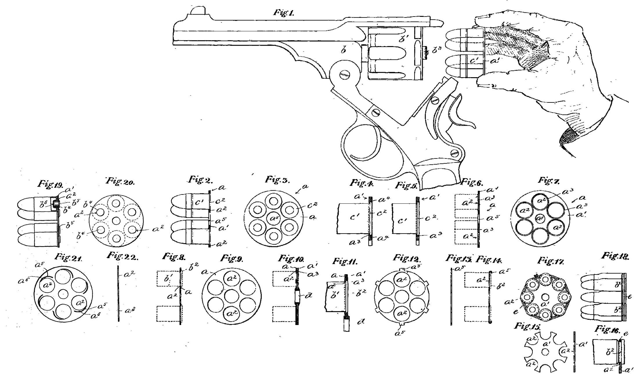
Figure 1 of the accompanying drawings is a view showing a revolver pistol in the act of being loaded with a full charge of cartridges held together in a coupler attachment constructed according to one form of my invention in which the cartridges are tightly fixed to the coupling disc so as to admit of them being both collectively loaded into and collectively ejected from the chambers of the revolver through the medium of the said disc. .
Figure 2 is a vertical section of this form of single disc coupler, with some of the cartridges in elevation.
Figure 3 is an elevation of the disc and cluster of cartridges.
Figure 4 represents upon an enlarged scale, a section of a part of the coupler disc, with one of the cartridges in elevation, showing how the cartridges are secured to the disc.
Figure 5 is a similar view to Figure 4, but shows the cartridge rim or head lying loose within its seating or recess in the disc, and before the cartridge and disc are secured together. ‘
Figure G is a section of the coupler disc separately, upon the same scale as Figures 2 and 3 and Figure 7 is an elevation of the one side.
The same -letters of reference indicate corresponding parts in the said Figures 1 to 7.
a is the disc or coupler which consists of a thin flat plate a1 of brass, steel ot other metal or material, preferably of less diameter than the cylinder b1 of the revolver b in connection with which the coupled or clipped ammunition is to be used. The said plate is pierced or provided with a circular ring of holes a2, corresponding in number and positions to the chambers of the revolver and of such diameter that the bodies e1, of the cartridges shall fit fairly tight therein. To admit of the heads or rims c2 of the cartridges lying flush within th,o disc, the metal surrounding the holes is ahnularly recessed at a3 to form seatings for the reception of the said heads or rims, so that the disc, when in position, between the back of the cylinder and the front of the standing breech of the revolver, will occupy practically no more space than is ordinarily taken up by the heads or rims of the cartridges themselves. When it is desired to securely affix the cartridges to the coupling disc so that they may only be removed collectively from the revolver chambers, then the metal at the outer circumferential edges of the recesses or seatings may be turned or closed over (either at points or continuously) to a slight extent onto the edges of the rims as indicated at a* in Figure 4. If however provision is to be made for separately extracting any individual cartridge of the coupled cluster, then this closing over of the metal is dispensed with and the cartridges are retained in position only by reason of the tightness with which their bodies fit into the holes in the disc. A central opening as is formed in the centre of the disc to pass freely onto the back end b3 of the revolver extractor pin.
In some cases, where individual as well as collective extraction is to be provided for, the backs of the holes need not be recessed to foim seatings for the flush reception of the cartridge heads. Sucli ‘an arrangement of disc is showix in section in Figure 8 and in elevation in Figure 9. a is the coupler disc which is plain or unrecessed at both back and front, and a2 are the ring of holes into which the bodies b1 of the cartridges fit with any desired degree of tightness whilst their rims b2 abut and lie against the back of said disc as shown by the dotted lines in Figure 8.
Figure 10 is a.vertical section of another form of coupler attachment in which provision is made for. collective extraction only, as the cai*tridges are permanently secured to the coupler.
Figure 11 is a section of a part of the said coupler upon an enlarged scale.
In. this modification, the coupler is made up of two circular discs or plates a and a1, each provided with a ring of coincident holes a2 and a3, corresponding in number and position to the cylinder chambers, the holes a? in the front plate being of such diameter as to fit tightly onto the bodies ft1 of the cartridge,
. whilst the “holes a3 in the back plate are of less diameter than the cartridge heads fta, which are confined and held between the two plates, these latter being secured together by means of an eyelet d, or by a rivet, shouldered bush or other connection which will hold together the plates and cartridges.
In another arrangement, the cartridges may be retained within their respective holes in . the coupler by clips or turned over parts. Thus, the coupler disc may be made of the form shown in elevation in figure 12, and in edge view in Figure 13, with a teat or projection a5 standing from the edge adjacent to each of the holes a2, ‘and after the cartridges have been forced home into the said holes, with the heads b2, abutting against the back of the plate, these projections are turned over so as to clip the heads of the cartridges and thus secure them to the plate as shown in section in Figure 14. ‘
In couplers for Mauser cartridges and other rimless or headless cartridges, -the coupler may be made in the form shown in elevation and edge view in Figure 15, which consists of a thin flat metal disc a1, with a series of open topped seatings or recesses aS cut around the outer edge in positions which correspond to the chambers of the revolver, The necks b2 of the cartridges are engaged with or laterally introduced into these seatings, as shown upon an enlarged scale in Figure 10, and there retained by means of an elastic or other cord e, or ,a wire or the like passed round the outsides of the whole of the cartridges and taking into the necks thereof so as to secure the whole of the cartridges in a cluster to the loading plate as represented in back elevation in Figure 17 and in side view in Figure 18.
Another alternative, which is applicable to -both headed and rimless cartridges but which admits of collective extraction only, is shown in vertical section in Figure 19 and in back elevation in Figure 20. In this arrangement the percussion caps of the cartridges form the means of permanently securing the said cartridges to the coupling plate or disc. Thus the holes a? in the coupling plate a1 correspond to the diameter of the caps ft4, which fit tightly with said holes and have rims or heads ft5 at their outer or back ends. Those caps are driven or forced through the holes a3 before being passed into cap chambers ft8 of the cartridge and thus the plate is secured between the rims of the caps and the rims or back ends of the cartridge and is thus connected to and couples together the cluster or group of cartridges comprising the full revolver charge.
In order to hold the cartridges securely to the coupling plate and yet admit of individual extraction, the said coupling may be made in the form shown in elevation in Figure 21, and in section in Figure 22. In this arrangement, the metal adjacent to each of the cartridge holes a2 is pierced with a curved or other slit a3, which leaves a spring tongue a6 capable of exexting a slight frictional grip when slightly displaced by the cartridge on the latter being forced home.
Having now particularly described and ascertained the nature of our said invention, and in what manner the same is’to be performed, we declare that what we claiin is ;(—
First—A quick-loading or charging coupler or clip for use in connection with cartridges for revolvers and magazine fire airms, consisting of a thin disc or plate of metal or other material to which the cartridges are directly secured or connected in groups or clusters so as to enable the full charge of cartridges to be collectively loaded into the chambers and collectively extracted, or to admit of either collective extraction or the selective extraction of any individual cartridge, substantially as herein described and also as set forth in* the accompanying drawings.
Secondly;—A quick-loading or charging coupler or clip attachment for the cartridges of revolvers and magazine fire-arms, consisting of a thin disc or plate of metal or plate of metal provided with a series of holes or recesses corresponding in number and disposition to the chambers of the weapon to be collectively charged and within which the cartridges are fixedly or detachably held or secured, in the manner or by the means substantially as herein described and also as set forth in Figures 1 to 9, 12 to 14, 15 to 18, 21 and 22.
Thirdly:—The modified form of quick-loading or charging coupler or clip attachment for the cartridges of revolvers and magazine fire arms in which the heads of rims of the cartridges are held between a pair of perforated or pierced discs or plates, secured together by an eyelet, rivet or other connection, substantially as and for the purpose herein’ described and set forth in Figures 10 and 11.
Fourthly ;—The modified form of quick-loading or charging coupler or clip attachment for the cartridges of revolvers and magazine fire-arms consisting of a disc or plate of metal or other material to which a group or cluster of cartridges is directly secured throuerh the medium of their percussion caps, substantially as and for the purpose herein described and set forth in Figures 19 and 20.
Dated this 10th day of June 1902.
. TEE WEBLEY & (SCOTT REVOLVER AND ARMS COMPANY LIMITED,
WILLIAM JOHN WHITING
By Henry Skerrett
24 Temple Row Birmingham Agent for Applicants.