
Britain 17291
№ 17,291 A.D. 1896
Date of Application, 5th Aug., 1896
Complete Specification Left, 4th May, 1897-— Accepted, 17th duly, 1897
PROVISIONAL SPECIFICATION.
Improvements in Revolver Firearms.
I, William John Whiting, of 153, Linwood Road, Handsworth, in the County of Stafford, Foreman of Works, do hereby declare the nature of this invention to be as follows :—
My invention relates to improvements in mechanism for holding and releasing the cylinders of revolving firearms of those types which open on a hinged joint for loading and extracting; and my present invention is a further development of, and improvement upon, my previous invention, for which Letters Patent 3427 A.D. 1891, were granted to me.
The objects of my improvements are:—
(1) To securely hold the cylinder during the action of the extractor mechanism;
(2) To allow free rotation of the cylinder when shooting; and
(3) To enable the user to easily dismount the cylinder from the axis, and remount it on the same when required.
These three objects were secured by my previous Letters Patent above quoted, but my present improvements secure several advantages, the most important of which is absolute safety against accidental loss of the revolver cylinder when opening the revolver for the extraction of the empty cases and reloading.
By my present improvements the efficiency of the revolver is more independent of wear and tear by use, that is to say, the revolver, as constructed on my latest improvements cannot get out of order in any one of the three essential points above named by any amount of wear and tear such as can occur during the life of the revolver.
These requirements are fulfilled in the following manner;
The revolver cylinder is mounted on a plain axis which is firmly fixed into the lump of the barrel.
The shoulder inside the cylinder abuts against the rear end of this axis to prevent the undue forward movement of the cylinder; and its backward movement is prevented by a teat which comes nearly into contact with the standing breech when the arm is closed.
The cylinder is not otherwise fastened to the axis.
On the front end of the cylinder is a short, tubular projection or sleeve surrounding the axis, which axis is fixed into the lump of the barrel: and in this sleeve a groove is cut for the purpose hereinafter described, namely, the holding and releasing of the cylinder as required.
So far, my present invention corresponds with the invention in my previous specification; but my present invention aims at removing certain difficulties which experience has pointed out in regard to my said-previous invention.
In my present invention on the lump of the barrel I pivot a stirrup shaped lever which embraces both sides of the lump and the cross bar of which stirrup passes across the revolver between the front end of the cylinder and the rear end of the lump on the barrel.
This cross bar is hollowed out to suit the curve of the groove in the before mentioned sleeve for the purpose of locking the cylinder when required.
For convenience of description I shall speak of this stirrup shaped lever as the “stirrup.”
This stirrup is operated by the same mechanism as that shown in my above mentioned previous specification, but its action is supplemented by the further mechanism now about to be described, which further mechanism secures as before stated a greater certainty of action to hold the cylinder, allow free rotation, and release the cylinder when required, as stated in the third. paragraph of this specification.
This extra efficiency is obtained in the following manner:—
On the periphery of the knuckle joint of the body a rounded part of the cross bar of the stirrup rides, and so-long as this rides on the full circumference of the joint the stirrup is in positive engagement with the groove in the sleeve before mentioned, and the cylinder is absolutely locked in position, and cannot be lost.
At two positions of the knuckle joint grooves are cut across the knuckle joint to allow of the unlocking of the cylinder; that is to say, that at those two positions the rounded part of the cross bar of the stirrup can drop into the grooves provided, and then the cylinder is free.
The relative positions of these two grooves to free the cross bare are:—
(1) When the revolver is fully closed.
(2) When the revolver is fully open:
but there is this difference; when the revolver is closed the stirrup is withdrawn from engagement with the sleeve in order to give perfect freedom of rotation to the cylinder in shooting, but when the revolver is fully open the stirrup locks the cylinder unless the user desires to free the cylinder by moving the disengaging lever when the stirrup is drawn out of gear and the rounded part of the cross bar of the stirrup drops into the groove provided and the cylinder is free.
But in any case, on moving the revolver from the closed to the open position or vice versa, the full circumference of the body joint absolutely ensures the safe locking of the cylinder.
A serviceable modification of the stirrup fastening for the cylinder consists of the following mode of construction:—
The stirrup is made wider between its arms than the lamp on the barrel.
This gives it a freedom of transverse motion.
It is always pressed to one side of the revolver by a spring and then locks the cylinder, but if pressed in’ the contrary direction, the cylinder is set free. A part of the stirrup fastener and a part of the body of the revolver are each bevelled in order that on closing the revolver the transverse sliding stirrup may automatically move sideways so as to free the cylinder for shooting.
Also to facilitate the replacement of the cylinder after dismounting the front part of the stirrup is chamfered.
Dated 31st day of July 1896.
WILLIAM JOHN WHITING.
COMPLETE SPECIFICATION.
Improvements in Revolver Firearms.
I, William John Whiting of 53 Douglas Road, Handsworth in the County of Stafford, Works Manager, do hereby declare the nature of this invention and in what manner the same is to be performed, to be particularly described and ascertained in and by the following statement:—
My invention relates to improvements in mechanism for holding and releasing the cylinders of revolver firearms of those types which open on a hinged joint for loading and extracting; and my present invention is a further development of, and improvement upon my, previous invention, for which Letters Patent No. 3427 A.D. 1891 were granted to me.
The objects of my improvements are:—
1. To securely hold or retain the cylinder upon its axis during the operation of the extractor mechanism.
2. To allow free rotation of the retained cylinder when firing.
3. To enable the user to easily dismount the cylinder from the axis and remount it on the same when required.
These three objects were secured by my previous Letters Patent above quoted; but my present improvements secure several advantages, the most important of which is absolute safety against accidental loss of the revolver cylinder when opening the revolver for the extraction of the empty cases and reloading.
By my present improvements the efficiency of the revolver is more independent of wear and tear by use; that is to say, the revolver, as constructed on my latest improvements cannot get out of order in any one of the three essential points above named by any amount of wear and tear such as can occur during the life of the revolver.
These requirements are fulfilled in the following manner:—
The revolver cylinder is mounted on an axis which is firmly fixed into the lump of the barrel.
The shoulder inside the cylinder abuts against the rear end of this axis to prevent the undue forward movement of the cylinder; and its backward movement is prevented by a teat which comes nearly into contact with the standing breech when the arm is closed for firing.
The cylinder is not otherwise fastened to the axis.
On the front end of the cylinder is a short, tubular projection or sleeve surrounding the axis, which axis is fixed into the lump-of the barrel as before stated; and in this sleeve a groove is cut for the purpose hereinafter described viz.:— the holding and releasing of the cylinder as required, by means of the special mechanism to be described.
So far my present invention corresponds with the invention in my previous specification; but my present invention aims at removing certain difficulties which experience has pointed out in regard to my said previous invention.
In my present invention on the lump of the barrel I pivot a stirrup or flattened U-shaped lever hereinafter called the stirrup which embraces and is jointed to both sides of the lump, and the cross bar of which stirrup passes across the revolver between the front end of the cylinder and the rear end of the lump on the barrel. This cross bar is hollowed out to suit the curve of the groove in the before-mentioned sleeve on the cylinder, with which it engages for the purpose of locking the said cylinder when required.
This stirrup is operated in part by like mechanism to that described in my above mentioned previous specification, but its action is supplemented by the further mechanism now about to be described; which further mechanism secures as before stated a greater certainty of action to hold or retain the cylinder on the axis, allow free rotation thereof and release the said cylinder, when required as above referred to.
This extra efficiency is obtained in the following manner:—
On the periphery of the knuckle joint of the body the underside of the cross bar of the stirrup rides, and so long as this bar wipes over the full circumference of the joint the stirrup is retained in positive or full engagement with the groove in the sleeve of the cylinder before mentioned, and the cylinder is absolutely locked in position and cannot be lost during the opening and closing of the revolver.
At two positions of the knuckle joint, two sets of transverse grooves are cut across the knuckle joint: to respectively allow of the unlocking and parallel freeing of the cylinder; that is to say, that at those two positions the underside of the cross bar of the stirrup can drop into the grooves provided, and then the cylinder is either free by the dropping of the cross bar into a deeper groove, or the stirrup is removed from actual contact with the bottom of the annular groove in the sleeve to admit of the cylinder freely revolving, by the dropping of the cross bar into the shallower, groove.
The relative positions of these two grooves for admitting of the cross bar fully or partially dropping are such that when the revolver is fully closed the deeper grooves in the barrel knuckle cheeks come lignable with the shallow grooves in the body knuckle cheeks, but when the revolver is fully opened the deeper grooves in the cheeks of both knuckles come coincident and so that when the revolver is closed the stirrup is withdrawn from engagement or contact with the bottom of the groove in the sleeve in order to admit of perfect freedom of rotation to the cylinder in shooting, but when the revolver is fully open the said stirrup locks the cylinder unless the user desires to free it by moving the disengaging-lever, when the stirrup is taken out of gear and the underside of the cross bar of the same drops into the deeper sets of grooves provided, becomes clear of the groove in the sleeve and the cylinder is free, and can be removed from the axis. But in any case, on moving the revolver from the closed to the open position or vice vera the wiping of the underside of the stirrup cross bar over the full circumference of the body joint absolutely ensures the safe locking of the cylinder, by pressing the stirrup into engagement with the sleeve on the cylinder throughout the opening movement, which is owing to there always being a fixed distance between the full circumference of the knuckle and the bottom of the annular groove.
A modification of the stirrup fastening for the cylinder-consists of the following mode of construction:— The stirrup is made wider between its arms than the lump on the barrel, so as to give it a freedom of transverse motion. It is ‘always pressed to one side of the revolver by a spring and then locks the cylinder, but if pressed in the contrary direction the cylinder is set free. A part of the stirrup fastener and a part of the body of the revolver are each bevelled in order that on closing the revolver the transverse sliding stirrup may automatically move sideways so as to free the cylinder for shooting.
Also to facilitate the replacement of the cylinder, after dismounting, the front part of the stirrup is chamfered.
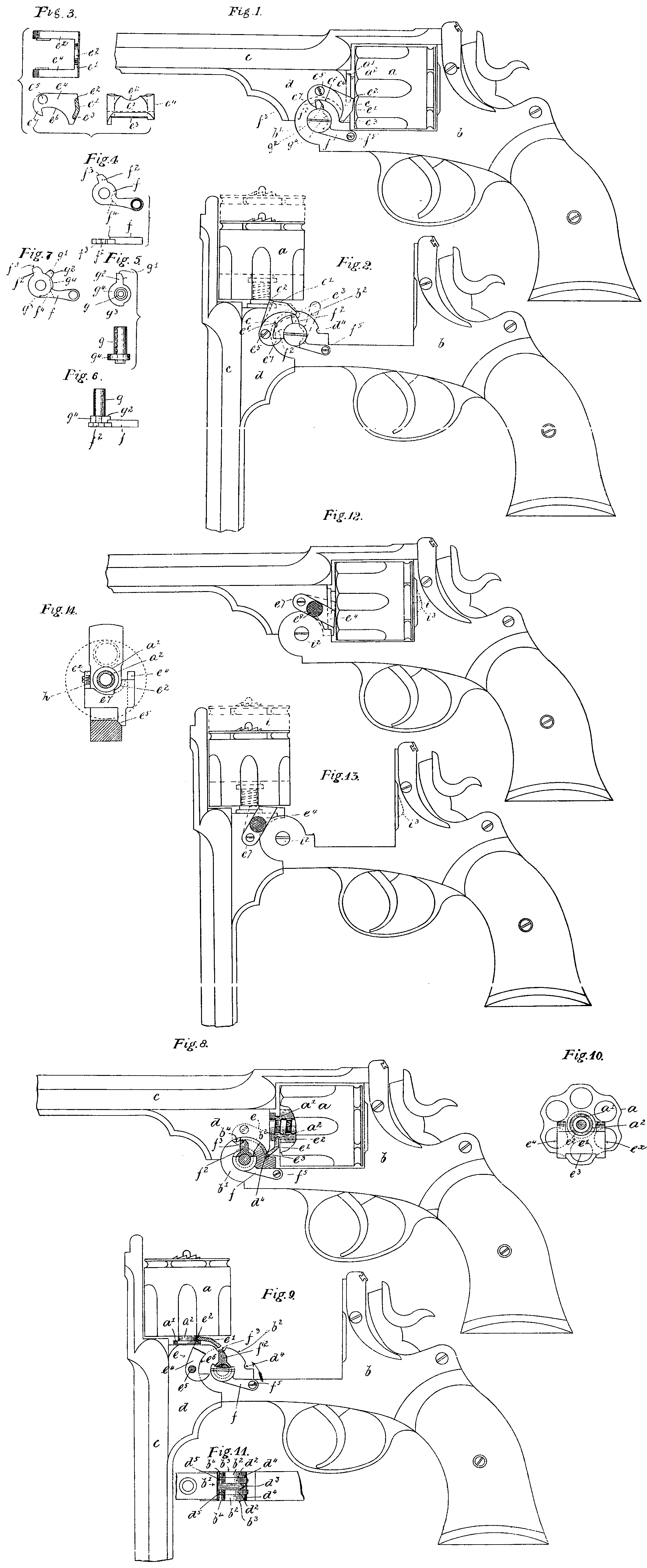
The accompanying drawings show my invention, in both forms, applied to revolvers, and also parts of the mechanism separately.
Figure 1 represents a complete side elevation of a revolver provided with the first form of my improved mechanism for holding, releasing and freeing the cylinder. The said revolver is shown closed and the cylinder locked through the medium of the bar of the pivoted or swinging stirrup, but partially freed in order to admit of the free rotation of the same around its axis.
Figure 2 represents the said revolver opened, as-for extracting and ejecting the fired cartridge cases and reloading and with the underside of the stirrup cross bar shown fully engaged with the groove in cylinder sleeve, thus locking the said cylinder to its axis.
Figure 3 represents a topside plan transverse section and back elevation of the swinging stirrup separately.
Figure 4 is aside elevation and edge view of the double-armed disengaging lever, the short arm of which constitutes a lug for both keeping the stirrup in engagement with the annular groove in the sleeve at the front of the cylinder, and also for giving a partial turning movement to the said stirrup for disengaging the stirrup cross bar from the said groove.
Figure 5 represents an end view and plan of the pivot. axis passing through the knuckle joint, having a wiper or bossed end the edge of which carries or is formed into a lug and a shoulder. The former is made to drop into a sinking on the outer face of the joint, so as to make the pivot rigid with and move with the lug, whilst the shoulder forms a stop for limiting the movement of the disengaging lever, which is fitted on to the end thereof, as shown in edge view in Figure 6 and in front elevation in Figure 7.
Figure 8 represents a like view of the revolver as Figure 1, but the front end of the cylinder and sleeve, and also the stirrup and a part of the joint shown in section.
Figure 9 represents a like part sectional view as Figure 8, but with the revolver opened as in Figure 2.
Figure 10 represents an end elevation of the cylinder, with the sleeve in section and with the stirrup engaging with the groove in elevation.
Figure 11 is a plan of the joint showing the sets of transverse grooves.
The same letters of reference indicate corresponding parts in Figures 1 to 11 of the drawings.
a is the cylinder of the revolver, b the body, c the barrel, and d the lump on the barrel, jointed to the knuckle b¹, of the said body. e is the stirrup for holding, freeing and releasing the cylinder as and when required, comprising a cross bar e¹, with the top edge e², formed to engage with the annular groove a², cut in the sleeve a¹, on the front of the cylinder a, whilst the underside edge e³, adapted to wipe over the peripheries b², d², of the cheeks b³, d³, of the knuckle joint b¹, and to fall into the sets of cross grooves or transverse sinkings d⁴, d⁵’, b⁴. The grooves d⁴, which are cut only in the outer cheeks, are simply for freeing the cross bar from frictional contact with the bottom of the groove in the cylinder sleeve so as not to impair the free rotation of the cylinder, whilst the other set of grooves b⁴, d³, when coincident as in Figure 11, allow the stirrup to fully drop so that its bar may become fully clear of the annular groove in the sleeve on the cylinder requiring to be removed from its axis. The said cross bar e¹, is carried by opposite side arms e⁴, eˣ, pivotedly hung at e⁵, and having their underside edges e⁶, curved to a radius struck from the same centre as the peripheries of the knuckles, so that on the wiping of the end f³, of the lug f², of the disengaging arm f, under the cam formation e⁶, the bar of the said stirrup is kept constantly in engagement with the annular groove a², of the sleeve a¹. The front end of one of the sides has a hook shaped shoulder or stop e⁷, which, when the lug f² is brought into direct contact with it, turns the said stirrup upon its joint centre e⁵ and disengages the edge e², from the groove in the cylinder sleeve. The disengaging lever has upon the back of it a shoulder f⁴, for limiting its movement by coming in contact with the shoulder g³, of the wiper or bossed end g⁴, of the pivot axis g, the inside face of whose lug g², partly lies within a like shaped sinking in the face of the knuckle, so that the said wiper or bossed end and the pivot axis is made rigid to, and compelled to turn with, the body of the arm. It is also understood that the contact end g¹, of the lug g², also travels upon the underside e⁶, of the arm e⁴ and constitutes a supplementary safety means for keeping the cross bar home should the disengaging lever become accidentally detached or fail, from any cause, to properly carry out the duties assigned to it.
OPERATION
On opening the revolver the following functions are performed by the various parts.
As the opening action begins, the lug g², of the wiper or boss g, moves away from the stop e⁷ of the stirrup e, leaving the same free. The cross bar e¹, then moves out of the groove d⁴ in the knuckle of the body, and on to the circumference or periphery b², d², of the body joint. Thus the part e² of the stirrup e is put into gear with the groove in the cylinder sleeve and held there during the whole of the opening movement, thus securely holding the cylinder in position on its axis. But when the grooves b⁴, d³, across the knuckle joint of the lump coincide, then the bottom edge e³, of the cross bar is in position for falling into them and which, when dropped, would leave the cylinder free to slide off its axis and incur the risk of loss. Such a contingency is guarded against by the action of the lever f, in following manner. While the revolver is being opened, the tip end f³, of the lug f² of the lever f, and the tip end g¹, of the lug g², of the wiper g¹ are made to travel along the cam curve e⁶, of the stirrup side, towards the cross bar end of the same, but with the traverse of the lug g², exceeding that of the lug f². When in this position the said lug f², acts as a strut and securely holds the stirrup e, in such a position that the part e² engages the groove of the cylinder sleeve. The two lugs f², g² are only employed in double order as a precaution in case of the failure of either of them.
If the cylinder is to be freed for dismounting, the lever f, is moved by hand to the position shown by the dotted outline in Figure 2 after being released from the body by the withdrawal of the small screw f⁵. It will be seen that the lug f², then acts on the stop end e⁷, of the stirrup, and rocks the same, thereby freeing the cylinder as indicated by the dotted outline of the latter.
If the dismounted cylinder be replaced on the axis, the lever f, need not be set by hand, as the mere closing of the revolver will bring all the parts to the position shown in Figure 1. Equally, if the cylinder be not. dismounted, and the revolver be closed from the positions shown in full lines in Figure 2 the conditions of Figure 1 will be restored by the said act of closing.
The small supplementaly screw f³, is not absolutely necessary for securing the disengaging lever to the lump in the barrel.
In Figures 12 and 13 is shewn a revolver with stirrup constructed according to the modified form of my invention.
Figure 14 is an elevation of the stirrup separately but shown in conjunction with the front end of the barrel, the sleeve of which is in section.
In this case the stirrup is wider between the arms e⁴ and eˣ than the knuckle joint. A spring h presses the stirrup towards the left side, and (when the revolver is opened) brings the curved part or lip e² into the groove a² of the cylinder sleeve a¹. Pressing on the chequered button e⁴ releases the cylinder.
In order to free the cylinder for firing, a slight chamfer e⁵, may be formed on the right side of the body-b, to push the stirrup e⁷ a little to the right when the revolver is closed, and keep it so until the revolver is again opened. After the opening of the revolver to a limited extent, then the stirrup e⁷, is released and the engaging lip e² carried by it is made to enter the annular groove a², on the sleeve a¹ of the cylinder which is thus locked when the revolver is fully opened.
Thus, on the first opening of the revolver, the teat i, at the back of the cylinder describes a radius from the joint i², within the vertical recess i³, in the standing breech, but just before the said teat leaves the said recess, the stirrup is released from its held back position and is then impelled by the spring and its lip e², is instantly taken into engagement with the groove a², of the sleeve a¹, of-the cylinder, which is thus locked to its axis during the whole of the further movement of opening.
As a further modification, the stirrup may have a part cross bar, lip or extension and be pivoted to, or swing from a pin, or the holster guides of the barrel and have a flange wherethrough a screw pin passes and taken into the lump when fixing the said stirrup in its locked position. The operation is to first swing the stirrup into position by hand and so make the lip or extension engage with the annular groove; then-make fast the stirrup by screwing home the small screw.
Instead of the cross piece of the stirrup engaging in an annular groove on the front of the cylinder, it may take over an annular shoulder or collar thereon.
Having now particularly described ‘and ascertained the nature of my said invention, and in what manner the same is to he performed, I declare that what I claim is :—
First:— In means for holding and releasing the cylinders of revolver small arms, a stirrup or equivalent member, (mounted upon or carried by the lump or other suitable part of the barrel) with a cross bar located between the opposed ends of barrel lump and cylinder and adapted to engage with or be disengaged from an annular groove or collar of the said cylinder.
Secondly:— A stirrup or equivalent member having a cross bar coming between the front end of a revolver cylinder and barrel lamp and carried by opposite side branches or arms pivotedly swinging from the said lump or breech end of the barrel, and which cross bar is raised.and lowered to engage with, and be disengaged from, an annular groove or collar on the cylinder, by mechanism actuated either by the opening or closing of the revolver, or by hand, substantially for the purpose described and set forth.
Thirdly:— The combination of the stirrup e with the lever f and wiper g⁴, and their subordinate parts, for the purpose of holding, freeing and releasing the cylinder as described.
Fourthly:— The combination. of the cross bar e¹ in a stirrup e with the freeing grooves in the knuckles of the body and lump, as described.
Fifthly:— The supplementary means for positively holding the stirrup in-engagement with the cylinder, in which the cross bar or equivalent part of the same rides upon, or wipes over the full circumference of the knuckle joint during the motion of opening and closing of the revolver.
Sixthly:— The combination of the cylinder and its sleeve having an annular groove sunken therein or a collar formed thereon, of the-knuckle joint formed by the body and lump and sunken with the freeing grooves, the full circumference between the said grooves, the stirrup e, cross bar e², lever f and wiper g⁴, acting for the holding, freeing and releasing of the cylinder as described and set forth.
Seventhly:— The modification of the stirrup pressed upon by a spring, and freed by automatic action by hand pressure, for the purposes as described and set forth in Figures 12, 13 and 14.
Dated this 3rd day of May 1897.
WILLIAM JOHN WHITING,
By Henry Skerrett,
24 Temple Row, Birmingham, Agent for Applicant.