
Britain 3987
A.D. 1868, 31st December. № 3987.
Revolving Fire-arms and Cartridges.
LETTERS PATENT to William Edward Newton, of the Office for Patents, 66, Chancery Lane, in the County of Middlesex, Civil Engineer, for the Invention of “Improvements in Revolving Fire arms, and in Cartridges for the same and for other Fire-arms,”— A communication from abroad by Ebenezer Howard Plant, Amzi Perrin Plant, and Alfred Hotchkiss, all of Southington, in the State of Connecticut, United States of America.
Sealed the 8th June 1869, and dated the 31st December 1868.
PROVISIONAL SPECIFICATION left by the said William Edward Newton at the Office of the Commissioners of Patents, with his Petition, on the 31st December 1868.
I, WILLIAM EDWARD NEWTON, of the Office for Patents, 66, Chancery Lane, in the County of Middlesex, Civil Engineer, do hereby declare the nature of the said Invention for “Improvements in Revolving Fire arms, and in Cartridges for the same and for other Fire-arms,” to be as follows:—
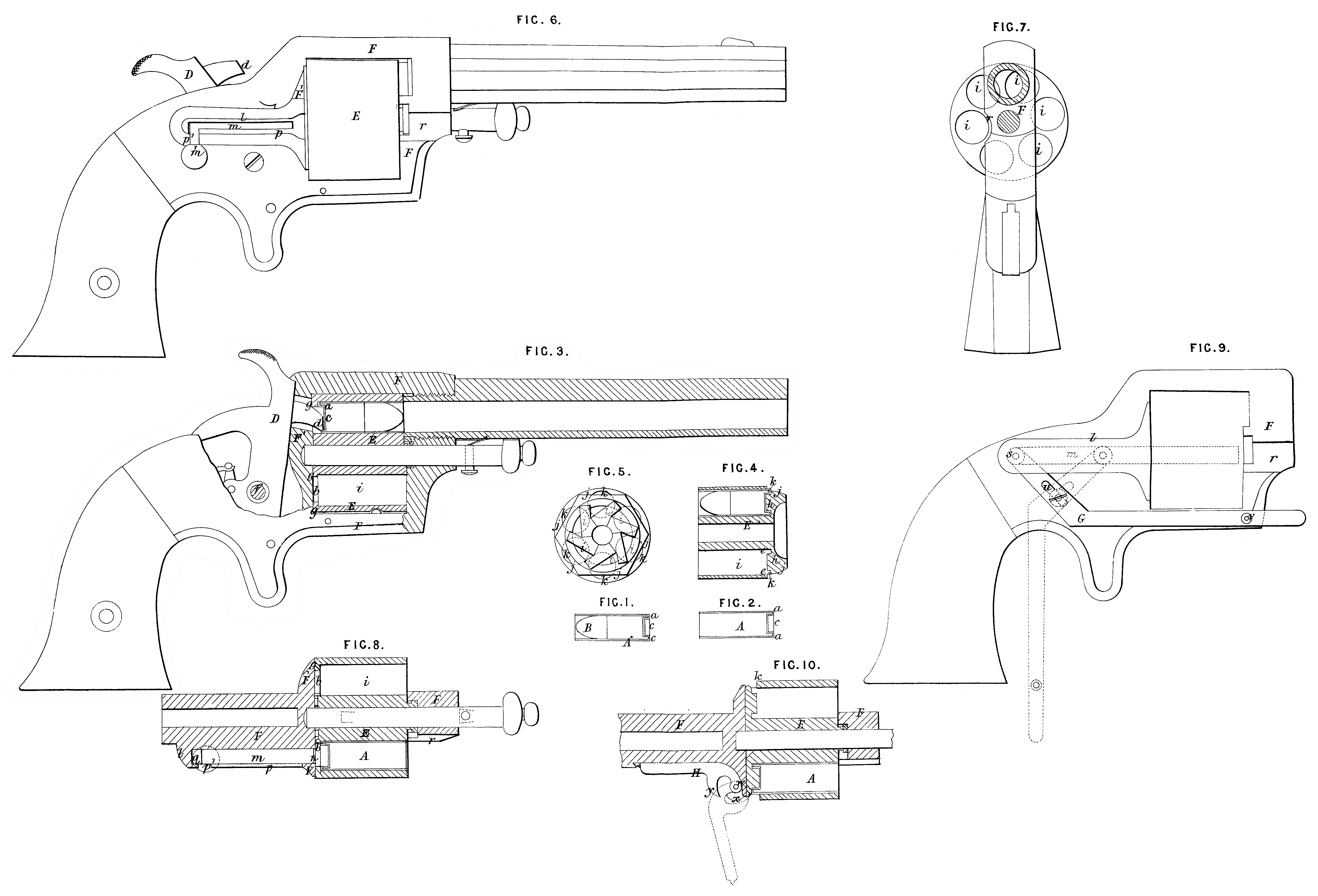
This Invention has for its object to provide for the loading of the chambers of the revolving many chambered cylinder of a revolving fire-arm with metal cased cartridges carrying their own fulminate priming by the insertion of such cartridges at the front of the cylinder, to provide for the firing of the cartridges so inserted, and to provide for the expulsion of the discharged cartridge cases from the cylinder in a forward direction.
The improvement in the cartridges consists in constructing a metal cased cartridge with a hollow flange around the rear end of its metal case. This hollow flange projects backward parallel or nearly so with the length of the cartridge, and has an external circumference no greater than the rest of the case. This flange contains a fulminate priming which may be fired by the hammer of the fire-arm striking through a suitable opening provided in the rear of each chamber of the< cylinder. The features of novelty in the revolving fire-arm are, constructing the rear portions of the chambers of the cylinder with openings through which the hammer may strike the cartridges. These openings are otherwise closed or partly closed to support the rear end of the cartridge. The loading of the arm with a metal cased cartridge carrying its own priming is effected at the front, and the firing of such cartridge is produced by the blow of the hammer upon the flange of its shell. Openings are made in the rear of the chambers of the cylinder, so that the hammer is enabled to strike upon the interiors of the flanges of cartridges such as those above mentioned. The cartridge case ejector consists of a plunger or piston arranged upon or in the frame or stock of the revolving fire-arm at the rear of the recoil shield through which a hole for its passage is made. This plunger or piston is provided with a projecting button or knob whereby it may be moved in and out, or this may be done by means of a slotted lever connected at one end to the piston or plunger. Another form of cartridge case ejector consists of a lever provided with a pointed wedge or cam piece which when the lever is moved down is inserted behind the flange of the case and pushes it forward. This lever is applied to the frame of a revolving fire-arm under the stock and in rear of the rotating chamber. SPECIFICATION in pursuance of the conditions of the Letters Patent, filed by the said William Edward Newton in the Great Seal Patent Office on the 30th June 1869. TO ALL TO WHOM THESE PRESENTS SHALL COME, I, William Edward Newton, of the Office for Patents, 66, Chancery Lane, in the County of Middlesex, Civil Engineer, send greeting. WHEREAS Her most Excellent Majesty Queen Victoria, by Her Letters Patent, bearing date the Thirty-first day of December, in the year of our Lord One thousand eight hundred and sixty-eight, in the thirty-second year of Her reign, did, for Herself, Her heirs and successors, give and grant unto me, the said William Edward Newton, Her special licence that I, the said William Edward Newton, my executors, administrators, and assigns, or such others as I, the said William Edward Newton,, my executors, administrators, and assigns, should at any time agree with, and no others, from time to time, and at all times thereafter during the term therein expressed, should and lawfully might make, use, exercise, and vend, within the United Kingdom of Great Britain and Ireland, the Channel Islands, and Isle of Man, an Invention for Improvements in Revolving Fire arms, and in Cartridges for the same and for other Fire-arms," being a communication to me from abroad upon the condition (amongst others) that I, the said William Edward Newton, my executors or administrators, by an instrument in writing under my, or their, or one of their hands and seals, should particularly describe and ascertain the nature of the said Invention, and in what manner the same was to be performed, and cause the same to be filed in the Great Seal Patent Office within six calendar months next and immediately after the date of the said Letters Patent. NOW KNOW YE, that I, the said William Edward Newton, do hereby declare the nature of the said Invention, and in what manner the same is to be performed, to be particularly described and ascertained in and by the following statement, reference being had to the Drawing hereunto annexed and to the letters and figures marked thereon (that is to say):— This Invention has for its object to provide for the loading of the chambers of revolving fire-arms with metal cased cartridges carrying their own fulminate priming by the insertion of such cartridges at the front of the cylinder, also to provide for the firing of the cartridges. so inserted and for the expulsion of the discharged cartridge cases from the chambers. The improvement in the cartridges consists in constructing a metal cased cartridge with a hollow flange a around the rear end of its metal case. This hollow flange projects backward parallel or nearly so with the length of the cartridge, and has an external circumference no greater than the rest of the case. This flange contains the fulminate priming which may be fired by the hammer of the fire-arm striking through a suitable opening provided in the rear of each chamber of the cylinder. The improvement in cartridges is illustrated in Figures 1 and 2 which represent a longitudinal section of a cartridge and cartridge case. A is the case of copper or other suitable metal of a sufficient length to contain the charge of powder and the whole of the ball B, and also to fill the whole length of the chamber of the fire-arm. This cartridge may be used not only in revolvers but also in breech-loading fire-arms. In either case the fire-arm must have the rear portion of the chamber or chambers so constructed that while being partially closed to prevent the cartridge from slipping out at the back, and also to support it against recoil in firing, the hammer will have sufficient room to enter and strike the flange and explode the fulminate priming. That part of the Invention which provides for the firing of the cartridges may be carried out in two different methods. One of these methods (see Figures 3 and 8 which represent respectively a longitudinal section of a revolving fire-arm and a horizontal section of the cylinder and frame) provides for striking the interior of the flanges of the cartridges. To effect this object the chambers i, i, in the cylinder E are provided with openings b directly through the rear of the chambers for the entrance of the nose d of the hammer D, and the hammer is arranged so that its nose may enter the chambers through the openings and strike upon the interiors of the flanges of the cartridges. These chambers i, i, are of a cylindrical or slightly taper form, and are bored from the front nearly to the rear or bottom of such chambers so as to leave only a suitable thickness of metal at the rear or bottom to support the cartridges A. The openings b in the rear of the chambers E may be concentric with or slightly eccentric to the chamber so as to leave a flange g all round the chamber of sufficient width to form a bearing for the flange a of the cartridge. The nose d of the hammer D is made with a downward dip, and the hammer is mounted on the pin f and so arranged that it may strike in a slightly downward direction through the openings b upon the interior of the flange a of the cartridge that contains the fulminate priming. In order to keep the cartridges always close against the flanges g of the chambers their cases are made of the full length of the chambers as before described, and the front of the frame F of the fire-arm is so constructed as to cover a portion of the front end of each chamber (say about the thickness of the cartridge shell) when the hammer is at full cock and during its fall, by this means the cartridges cannot be jarred out of place by the force of the explosion. The second method of providing for the firing of cartridges is shewn in Figures 4 and 5, which represent a central section and rear view of a cylinder in which the striking of the exteriors of the flanges is effected. A boss or projection h, Fig. 4, is made upon the interior of the rear of each chamber i to enter the cavity c (see Fig. 2) in the rear of the cartridge, and so form a support or anvil to sustain the flange a during the blow from the hammer. The rear end of each cylinder is cut away opposite to each chamber, as shewn at j, to form an opening k into the chamber through which the hammer of the fire-arm can enter to strike on the exterior of the flange a of the cartridge to effect the explosion of the charge. The hammer of the fire-arm may be applied in the usual or any other convenient manner. That part of the Invention which relates to extracting the discharged cartridge cases embraces three distinct improvements; the first of these improvements, shewn in Figures 6 and 7, which is a side and front view of a pistol, and Fig. 8 before referred to, is intended to be employed when a cylinder such as that represented in Figures 3 and 8 is used, and consists of a plunger m attached to and working in a slot or guide p cut in a swell or projection l upon the stock or frame F of the fire-arm and parallel with the chambers i. The plunger m is made to work through an opening n, see Fig. 8, in the recoil shield F¹, and is so arranged that the chambers i of the cylinder E are by turning the cylinder on its axis brought successively opposite to the opening n, and the plunger is moved forward into the chamber, and so pushes out the cartridge case. The plunger m is constructed or furnished with a knob or handle m¹, which when the plunger is drawn back clear of the cylinder fits into a notch p¹ at the rear end of the guide p. To make the handle secure that the plunger cannot be moved forward accidentally in this notch a spring q is employed (see Fig. 8), which may be composed of a small piece of vulcanized india-rubber or of coiled steel wire inserted between the rear end of the plunger m and the back of the slot or guide p of the swell l, and which presses the handle m¹ hard against the front of the notch p¹. On the same side of the frame F as the plunger m and in front of the cylinder is a shallow groove r (see Figures 6 and 7) to allow the cartridge cases to pass out of the chambers in a forward direction, when the latter are severally brought opposite to the plunger. When it is desired to expel the discharged cartridge shells from the chambers i the hammer is brought to half-cock, and the knob m¹ of the plunger m is raised out of the notch p¹. The cylinder E is then turned by hand, so as to present the several chambers successively opposite the plunger, and on each one being brought to this position the plunger is pushed forward through the opening b. When the cartridge case has been drawn out the plunger must be drawn back and a fresh cartridge may be introduced immediately; or the whole of the cartridge cases may be first pushed out, care being taken that the hammer always remains at half-cock. The second improvement relating to the extraction of the discharged cartridge cases consists in the employment of a slotted elbow lever G in connection with the plunger m for the purpose of operating the plunger. This improvement is shewn in Fig. 9, and is intended more especially for fire-arms of large size, in which considerable force may be necessary to push forward the cartridges in the chambers. In applying this improvement the plunger m is arranged as in the improvement previously described in a swell 7 on the side of the frame, but instead of this swell having a slot in the face, as shewn in Figures 6 and 8, it has a similar straight slot underneath for the entrance and passage of the lever G. This lever G is pivotted by a pin S to the rear end of the plunger, and works on a stationary fulcrum pin t secured to the lower part of the side of the frame F, and is slotted, as shewn at u, where the fulcrum pin passes through it. The elbow of this lever is formed below the fulcrum, so that when the plunger is drawn back the longer and forward arm of the lever lies beside the frame F (Fig. 9) parallel with the bottom thereof. The plunger m is pushed forward by pulling down the front end of the lever, and is drawn back again by raising the same. When the plunger is drawn back it is locked against accidental movement by a pin v on the inner face of the lever, which springs into a notch or hole in the side of the frame F. The third improvement for extracting the discharged cartridge cases is shewn at Fig. 10, and relates more especially to revolvers having a cylinder like that shewn in Figures 4 and 5, namely, an opening to the chambers through the side or periphery of the cylinder. This improvement consists of a curved lever H, which is secured by its fulcrum pin w in a mortise made in the side of the frame F and behind the cylinder. The frame is made with a protuberance x for the reception of the fulcrum pin w. This protuberance has within it a portion of the mortise for the reception of the lever, and is formed to receive the wedge y, which is of the same piece of metal with the lever when the lever is thrown back or when it is not in use, as shewn in black outline in the Drawing. In order to provide for the easy entrance of the point of the wedge y between the rear ends of the cartridge cases and the rears of the chambers the openings k, k, of the cylinder E (which are used for the entrance of the hammer as well as for the entrance of the cartridge extractor) are slightly bevilled in a backward direction. When the cartridge cases are to be ejected the cylinder is turned to present the chambers one at a time opposite the extractor, and every time one is so presented the lever H is moved forward, as shewn in dotted outline, and the wedge y enters between the rear end of the chamber i and the rear end of the cartridge case, and so starts the case forward. If the chambers and cartridge cases are made slightly taper a sudden forward movement of the ejector will throw the shell completely out of the chamber, otherwise after being started forward the shell may be pulled out by taking hold of its front end with the thumb and finger. Having now described the nature of the said Invention as communicated to me by my foreign correspondent, and having explained the manner of carrying the same into effect, I wish it to be understood that under the above in part recited Letters Patent I claim,— First. A cartridge having a metal case constructed with a hollow flange projecting from the rear thereof in a backward direction. Second. The various methods herein described of constructing the rear portions of the chambers of the cylinders of revolving fire-arms, and for the purposes described. Third. The several arrangements for the cartridge case extractor, as herein described. In witness whereof, I, the said William Edward Newton, have hereunto set my hand and seal, the Twenty-sixth day of June, in the year of our Lord One thousand eight hundred and sixty-nine. W. E. NEWTON. (L.S.)