
US 21188
UNITED STATES PATENT OFFICE.
W. H. ELLIOT, OF PLATTSBURG, NEW YORK.
IMPROVEMENT IN REVOVING FIRE-ARMS.
Specification forming part of Letters Patent No. 21,188, dated August 17,1858,
To all whom it may concern:
Be it known that I, Wm. H. Elliot, of Plattsburg, county of Clinton, State of New York, have invented a new and Improved Revolving Pistol; and I do hereby declare that the following is a full and exact description thereof, reference being had to the accompanying drawings and the letters of reference marked thereon, the same letters indicating the same parts in each figure.
The nature of my invention consists in the employment, combination, arrangement, and construction of the devices of a revolving or vibrating pistol in such a manner as to produce a very much more compact, safe, and convenient repeating pocket-pistol than has ever been made heretofore.
To enable others skilled in the art to make and use my invention, I will proceed to describe its construction and operation.
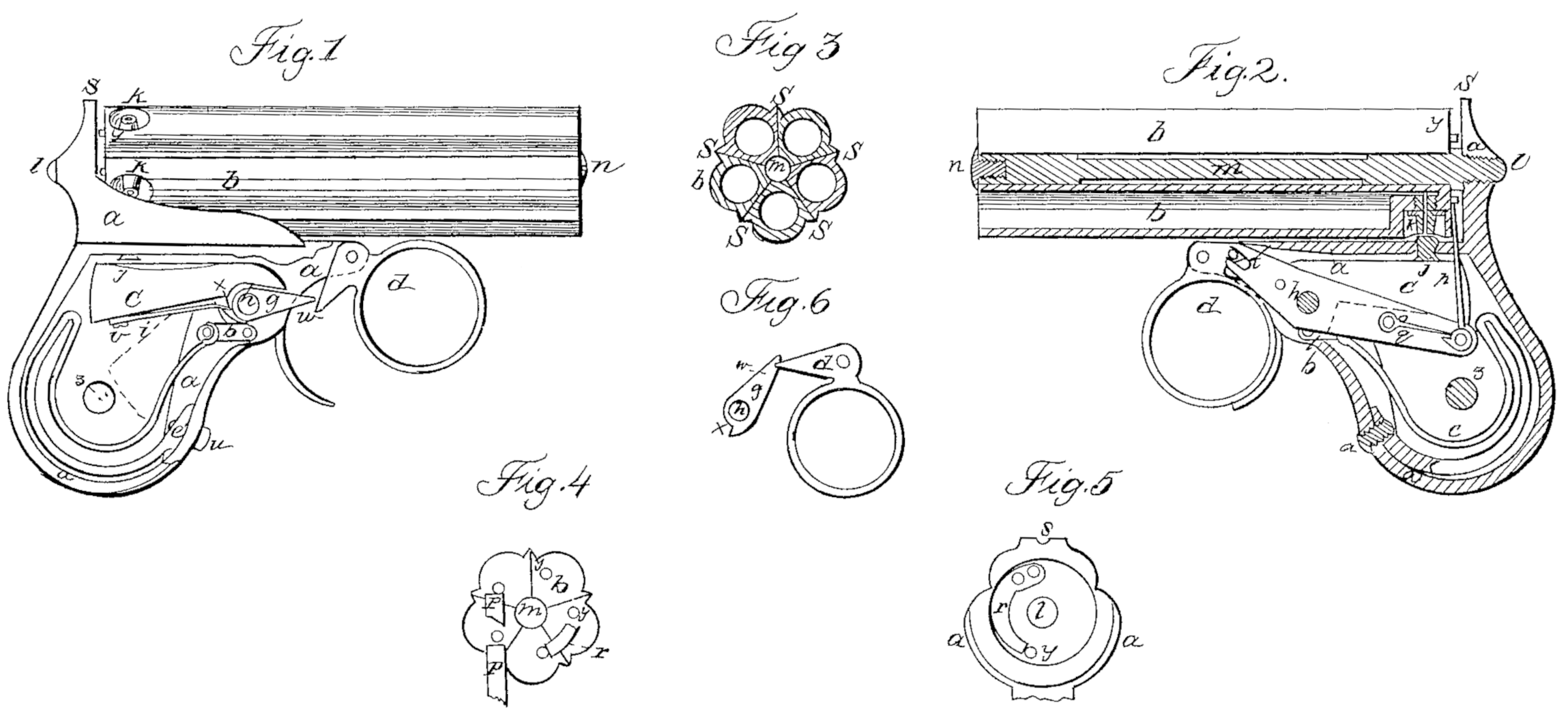
Figure 1 is an elevation of my pistol with one side of the stock and a portion of the frame removed for the purpose of showing the lock. Fig. 2 is a vertical section of the barrels, frame of the breech, center-pin, nipples, and mainspring, showing an elevation of the revolving devices with the lock behind them. Fig. 3 is an elevation of the muzzle, showing the manner in which the barrels are put together. Fig. 4 is an elevation of the rear end of the barrels, showing some of the revolving devices. Fig. 5 is an elevation of that portion of the frame immediately behind the part represented by Fig. 4, showing a spring-stop and a suction of the protecting wings or plate a’. Fig. 6 is an elevation of the fly and trigger, showing the position they occupy when standing cocked.
a a a represent the frame of the breech; a’, protecting wings or plate to guard the hands and lock; b b, barrels; e, cock; d, trigger; e, mainspring; f, stirrup;g, fly; h, pin upon which the cock, fly, and revolving-lever hang; i, fly-spring;j, movable pin;k, nipple; l, screw of center-pin; m, center-pin; n, screw for holding the barrels on the center-pin; o, revolving lever;p, revolving-dog; q, dog-spring;r, spring stop; s s s, sights; t, pin in side of trigger, carrying the revolving-lever; u, mainspring-screw; v, fly-spring screw; w, notch in fly for the point of the trigger to fall into, so as to hold the pistol cocked;x, projection on fly to receive its spring;y, revolving-pins in the rear end of the barrels; z, screw for holding the stock.
The operation of the lock and the revolving devices is as follows: When the trigger d is drawn back its point strikes the under side of the fly and raises it till the point of the trigger falls into the notch at w, as seen in Fig. 6. In this position it may be left standing, the cock occupying the position represented by the dotted lines, Fig. 1, or returned to its former position without firing by pushing the trigger forward, or it may be fired by drawing the trigger still farther back. In firing the point of the trigger passes out of the notch w over the end of fly g, when the fly and cock, by the power of the mainspring e, communicated through stirrup f, return to the position represented in Fig. 1 and explode the cap. The point of the trigger is now above the fly, and to prepare the lock to cock again the trigger must be pushed forward, and as it passes forward it depresses the fly without moving the hammer or cock until its point passes the fly, which immediately assumes, by the power of spring i, the position represented in Fig. 1. The lock is now ready to be cocked and fired again. When the trigger is pushed forward to readjust the lock the pin t in the trigger depresses the slotted end of revolving-lever o and raises the rear end of said lever, carrying with it the revolving-dog p. As this dog rises it catches against, a revolving-pin, y, as seen in Fig. 4, and carries the pin from the position represented by p to that represented by p’, thus causing the barrels to make one-fifth of a revolution, thereby bringing the next nipple directly over the cock. As the barrels assume the proper position for firing the stop-spring r, Fig. 5, slips over a revolving-pin as seen at r, Fig. 4, and holds the barrels from turning backward as the revolving-dog p is drawn back to catch the next pin. The spring-stop r also serves as a friction-spring while acting against the end of the barrels. When the trigger is drawn back in the act of firing the revolving lever o and dog p again assume the position represented in Fig. 2, the spring q causing the dog to catch the revolving-pins.
Among the peculiarities of this invention are: First. Extending the frame of the breech forward of the support of the center-pin at l, Fig. 2, to facilitate the arrangement of all the devices and hanging in the part so extended the cock and trigger, and also placing therein a portion of the revolving devices, the cock being arranged with its pivoted end nearest the muzzle of the barrels and its free end nearest the breech, and the trigger placed between the cock and the muzzles.
Second. The employment of a revolving-lever, which shall receive and transmit the power of the finger from the trigger in front to the revolving dog and ratch in the rear, and when connected, as above specified, directly with the trigger independent of the cock, and so as to revolve the barrels by the forward motion of the trigger. The finger is required to overcome the resistance of cocking only when drawing back the trigger and the resistance of revolving when pushing it forward. This lever may, without changing its arrangement, receive power indirectly from the trigger.
Third. The method of operating the cock by means of fly g, by which the resistance of cocking gradually decreases till the pistol comes to a full-cock, at which point it may stand till correct sight is taken, or it may be let down without firing by moving the trigger forward. This device, when used with a notch, w, gives the pistol the advantage of being cocked without firing or of being fired by a single motion of the finger and without loss of time in cocking.
Fourth. The employment of projecting wings a’, formed most conveniently by raising a portion of the frame for protecting the hands from injury by the discharging of gases and piece of caps from the nipples, and also for bracing the support of the center-pin.
Having thus fully described my invention, what I claim, and wish to have secured to me by Letters Patent, is—
1. Extending the frame of the breech forward of the supporting-point of the center-pin, and placing in the part so extended the cock c and trigger d, when these devices are arranged in relation to the several revolving barrels, as specified.
2. The arrangement of lever o and trigger d in advance of dog p and ratch y, by which the barrels are revolved, as and for the purpose specified.
3. The method of operating the cock c by means of fly g, the same being hinged at or near the center of motion of the cock and moving independently of the cock in one direction, but not in the other, as and for the purpose specified.
4. The employment of wing a’, when so constructed as to serve the double purpose of bracing the support of the center-pin and of protecting the hands from injury by the discharge of gases and pieces of caps from the nipples, and being a portion of the frame of the breech, asset forth.
VVM. H. IELLIOT.
Witnesses:
C. Haney,
G. F. Nichols.