
US 34093
UNITED STATES PATENT OFFICE.
WILLIAM JONES PITT, OF MIDDLETOWN, CONNECTICUT,
IMPROVEMENT IN REVOLVING FIRE-ARMS.
Specification forming part of Letters Patent No. 34,093, dated January 1, 1862.
To all whom it may concern:
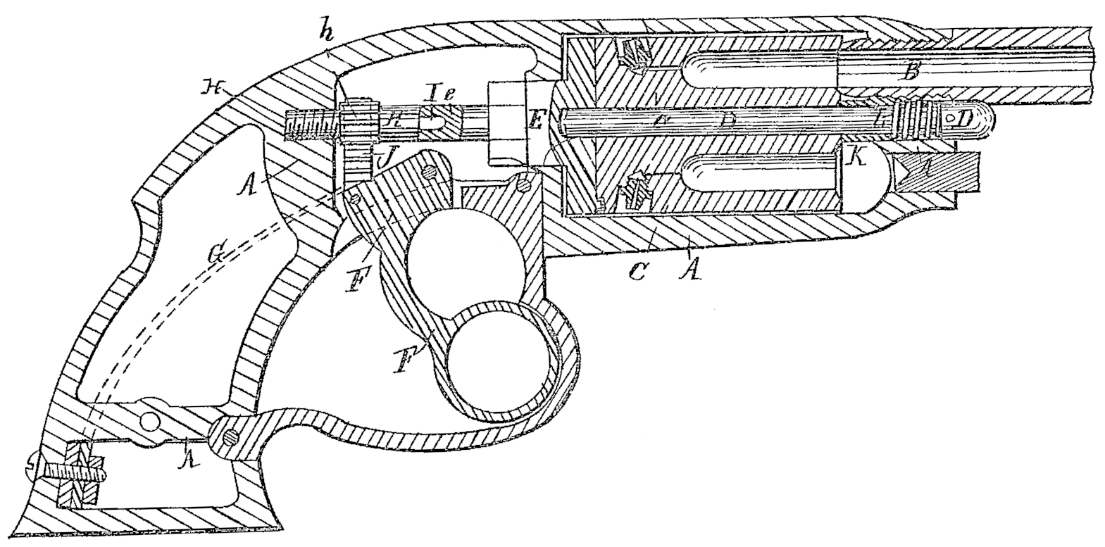
Be it known that I, William Jones Pitt, of Middletown, in the county of Middlesex and State of Connecticut, have invented certain new and useful Improvements in Revolving Fire-Arms; and I do hereby declare that the following is a full and exact description of the same, reference being had to the accompanying drawing, which is a longitudinal vertical section of a pistol with my improvements attached.
My invention relates to and is a means of removing the revolving chambers from contact with the barrel before they are rotated, and of forcing the one to be fired into firm contact therewith after being brought properly in line.
The nature of my invention consists in the employment of a male or female screw-thread on a part in line with the pin of the recoil-shield and connected therewith, rotated or partially rotated alternately in opposite directions through the intervention of a rack or equivalent means by the cocking-lever, or the lever which revolves the chambers, in such a manner that said threaded part shall recede and allow the chambers to be disconnected from or be removed from contact with the barrel previous to the action of the revolving pawl, and that when said cocking-lever is returned to its previous position the said screw shall force the clambers forward into firm contact with the end of the barrel, for the purpose of cutting of the windage and holding the chamber firmly in the line of the barrel.
The nature of my invention consists also in the arrangement of a washer or thimble in combination with the spring which forces the chambers back, and thus takes up the slack of the parts, whereby the said spring acts through the said thimble upon the front end of the revolving chambers, while it remains entirely concealed within the stock, out of reach of the powder or the deleterious gases which always escape to some extent between the chambers and barrel.
To enable others skilled in the art to make and use my invention, I will proceed to describe its construction and operation by the aid of the drawing and the letters of reference marked thereon.
A is the iron frame of the stock for a cavalry-pistol, and B the barrel attached thereto. C are the revolving chambers, supported by the pin D, and abutting against the recoil shield E. F is the cocking-lever, and G its spring, the lock and the parts connected therewith not being represented in this section. All the above-named parts are arranged similarly to several styles of arms heretofore known.
In a line with the pin e of the recoil-shield E, I place. a screw, H’, fitting a female screw in the stock A, and carrying a pinion, h, as represented. A pin, I, on the end of H enters a socket in the end of e, and forms a bearing for each, keeping them in line. A rack, J, is pivoted to the cocking-lever F, and meshes into the pinion h in such a manner that when F is worked back and forth the screw H is rotated and caused to recede into and advance from the stock A, thus giving the recoil-shield E a motion in the line of its axis.
The pin D, which forms an axis for the revolving breech or chambers C, has a bearing at one end in a socket, formed in the recoil-shield E, and at the other end in the stock A. The hole in the stock A is larger than that through the breech C, and the end of D is enlarged to fit therein, as represented. A thimble, K, with a diameter equal to that of the hole in A is fitted upon the pin D. One end of K bears against the end of the revolving breech C, while the other end extends a little way into A.
In the annular chamber formed in the hole in A, between the enlarged part of D and the thimble K, a helical spring, L, is placed, bearing upon K, and forcing it against the revolving breech C. When, therefore, the screw H recedes, the spring L, causes both C and the recoil-shield E to follow it, thus releasing C from B, and allowing it to be rotated by the proper mechanism (not represented) connected with the lever F. When the screw advances again the spring L is compressed, and C is again pressed into contact with B. A slot and pin (represented in dotted lines) prevent the thimble K from being removed from A when the pin D is withdrawn for the purpose of releasing the chambered breech, while it is allowed sufficient longitudinal motion to perform its proper functions.
I am aware that a reciprocating motion has heretofore been given to a revolving breech for the same purpose by means of a toggle joint, and also by a cam; but these are both objectionable from the rapid wear upon the joints of the one and upon the surface of the other. They are also more liable to derangement than my improved device.
I am also aware that a spring similarly situated to L has been used without the thimble K; but such spring was open, so that powder and dirt rapidly clogged it and prevented its proper action. A similar spring has also been placed within the chambered breech C, the hole in which was of two different diameters to allow of its reception; but such arrangement necessitated an enlarged hole in and a consequently weakening of the breech C, while it reduced the bearing-surface and increased the cost of manufacture, owing to the difficulty of boring the said hole with two different diameters, and of fitting the pin D so as to secure an equal and proper bearing at both ends. By the use of my thimble K the spring L is concealed in and protected by the stock A, while the bearing in C is retained in its simplest and other. They are also more liable to derange- most desirable form.
Having now fully described my invention, what I claim as new therein, and desire to secure by Letters Patent, is—
1. The combination and arrangement of the screw H, recoil-shield E, lever F, and rack and pinion J h, or their equivalents, substantially as herein set forth.
2. The arrangement of the spring L, thimble K, and pin D in and with the stock A, substantially as and for the purpose herein specified.
In testimony whereof I have hereunto set my hand in the presence of two subscribing witnesses.
W. J. PITT.
Witnesses:
Thomas D. Stetson,
G. H. Babcock.