
British 2921
Fire-arms, and Bullets and Waddings to be used therewith.
LETTERS PATENT to William Tranter, of Birmingham, in the County of Warwick, Gun Maker, for the Invention of “ Certain Improvements in Fire-arms, and in Bullets and Waddings to be
U8ED THEREWITH.”
Sealed the 22nd February 1854, and dated the 16th December 1853.
PROVISIONAL SPECIFICATION left by the said William Tranter at the Office of the Commissioners of Patents, with his Petition, on the 16th December 1853.
I, William Tranter, of Birmingham, in the County of Warwick, Gun Maker, do hereby declare the nature of the said Invention for “ Certain Improvements in Fire-arms, and in Bullets and Waddings to be used therewith,” to be as follows :—
My Invention consists, in the first place, in adapting & applying to guns or pistols to be loaded at the breech a plug or stopper to hold either a nipple or a tube, such plug or stopper being made in one or two parts, with a projecting lip to one or both, so as to be moved on a rod or pin. The plug or stopper is to be acted upon or retained by a suitable spring to hold it in its place, and also by a set screw.
It may also be formed with either a flat or conical joint next to the barrel. The frame in which the plug or stopper is inserted may be made either solid or in two parts, jointed at top and bottom & screwed together. The top strap may be fastened to the frame by means of a pin passing through the frame and strap, or it may be made solid with the frame.
And my Invention consists, secondly, in adapting and applying to guns and pistols of the same kind a revolving chamber, to be inserted in the frame above described instead of the plug or stopper, and acted upon by a set screw as above described, and also by a lock which may be described as follows:—In the present lock the main spring, trigger spring, and tumbler may be in principle similar to those of an ordinary lock, but will but will act in the middle of the frame instead of on a separate plate. The main spring may be placed either before or behind the tumbler. The trigger is made to act in the middle of the frame directly against the tumbler, and either before or behind the same. The tumbler for this lock may have a lever jointed to the arm to turn round the chamber. This lock may also be combined with the plug or stopper above described.
My Invention consists, thirdly, in the particular use of fat, oil, or wax, or other lubricating material, either with bullets, gun waddings, or cartridges, so as to be forced out of the same against the inner surface of the barrel by the explosion of the powder. The lubricating material may be placed either inside or outside the bullet, and for a gun wadding may be placed between two waddings or on the top of one, and for a cartridge it may be placed therein with only a thin material between it and the powder. The above described gun, when used for military purposes, may have a bayonet or sword fixed thereto by means of a bar of iron on the barrel, notched to hold the bayonet or sword, the latter being slotted in the middle of the handle, but with parts left to fit into the notches in the bar. There may also be a lever or catch, either with or without a spring, to fall into another notch in the bar, for the purpose of fixing the bayonet or sword on the barrel.
My Invention consists, fourthly, in forming oval or conical bullets with a hole through them in the centre in the direction of their length, which hole I prefer to be tapered, with the larger end of the taper in the front of the bullet.
And my Invention consists, lastly, in making bullets to be used with gun waddings in such a manner that; the tradding may be parted therefrom on the firing of the gun. For .this purpose the bullet is made hollow at the back, into which a leaden plug is made to fit, passing through the wadding, which plug fc forced through the wadding into the bullet on the explosion of the powder.
SPECIFICATION in pursuance of the conditions of the Letters Patent, filed by the said William Tranter in the Great Seal Patent Office on the 16th June 1854.” * »■-‘; <• v-
TO ALL TO WHOM THESE PBESHJfTS SHALL COME, I,
William Tranter, of Birmingham, in the .County of Warwick, Gun Maker, send greeting.
WHEREAS Her most Excellent Miyest; Queen Victoria, by Her Letters Patent, bearing date the Sixteenth day of December, in the year of our Lord One thousand eight- hundred and fifty-three, in the seventeenth year of Her reign, did, for Herself, Her heirs and successors, give and grant unto me, the said Willupn Tranter, Her special license that I, the said William Tranter, my: executors, administrators, and assigns, or such others as I, the said.-William Tranter, my executors, administrators, and assigns, should at any time agree with, and no others, from time to time and- at all t times thereafter during the term therein expressed, should and lawfully might make, use, exercise, and vend, within the United Kingdom of Great Britain and Ireland, the Channel Islands, and Isle of Man, an Invention for “ Cebtaix Impboyekehts nr Fibs-amis, Aim nr Bullets axd Waddihos to be used therewith,” upon the condition (amongst others) that I, the said William Tranter, by an instrument in writing under my hand and seal, should particularly describe and ascertain the nature of the said Invention, and in what manner the same was to be performed, and cause the same to be filed in the Great Seal Patent Office within six calendar months next and immediately after the date of the said Letters Patent.
NOW KNOW YE, that I, the said William Tranter, do hereby declare the nature of the said Invention, and in what manner the same is to be performed, to be particularly described and ascertained in and by the following statement, reference being had to the Drawings hereunto annexed, and to the letters and figures marked thereon (that is to say) :—
My Invention of “ Certain Improvements in Fire-arms, and in Bullets and Waddings to be used therewith,” consists, in the first place, in adapting and applying to guns or pistols to be loaded at the breech a plug or stopper to hold either a nipple or a tube, such plug or stopper being made in one or two parts, with a projecting lip to one or both, so as to be moved on a rod or pin. The plug or stopper is to be acted upon or retained by a suitable spring to hold it in its place, and also by a set screw. It may also be formed with either a flat or conical joint next to the barrel. The frame in which the plug or stopper is inserted may be made either solid or in two parts, jointed at top and bottom and screwed together. The top strap may be fastened to the frame by means of a pin passing through the frame and strap, or it may be made solid with the frame.
My Invention consists, secondly, in adapting and applying to guns and pistols of the same kind a revolving chamber, to be inserted in the frame above described instead of the plug or stopper, and acted upon by a set screw as above described, and also by a lock which may be described as follows:—In the present lock the main spring, trigger spring, and tumbler may be in principle similar to those of an ordinary lock, but will act in the middle of the frame instead of on a separate plate. The main spring may be placed either before or behind the tumbler. The trigger is made to act in the middle of the frame directly against the tumbler, and either before or behind the same. The tumbler for this lock may have a lever jointed to the arm to turn round the chamber. This lock may also be combined with the plug or stopper above described.
My Invention consists, thirdly, in the particular use herein-after described, of fat, oil, or wax, or other lubricating matter, either with bullets, gun waddings, or cartridges, so as to be forced out of the same against the inner surface of the barrel by the explosion of the powder. The lubricating material may be placed either inside or outside the bullet, and for a gun wadding may be placed between two waddings or on the top of one, and for a cartridge it may be placed therein with only a thin material between it and the powder.
The above described gun, when used for military purposes, may have a bayonet or sword fixed thereto by means of a bar of iron on the barrel notched to hold the bayonet or sword, the latter being slotted in the middle of the handle but with parts left to fit into the notches in the bar. There may also be a lever or catch, either with or without a spring, to fall into another notch in the bar, for the purpose of fixing the bayonet or sword on the barrel.
My Invention consists, fourthly, in forming oval or conical bullets with a hole through them in the centre in the direction of their length, which hole I prefer to be tapered, with the larger end of the taper in the front of the bullet.
And my Invention consists, lastly, in making bullets to be used with gun waddings in such a manner that the wadding may be parted therefrom on the firing of the gun. For this purpose the bullet is made hollow at the back, into which a leaden plug is made to fit, passing through the wadding, which plug is forced through the wadding into the bullet on the explosion of the powder.
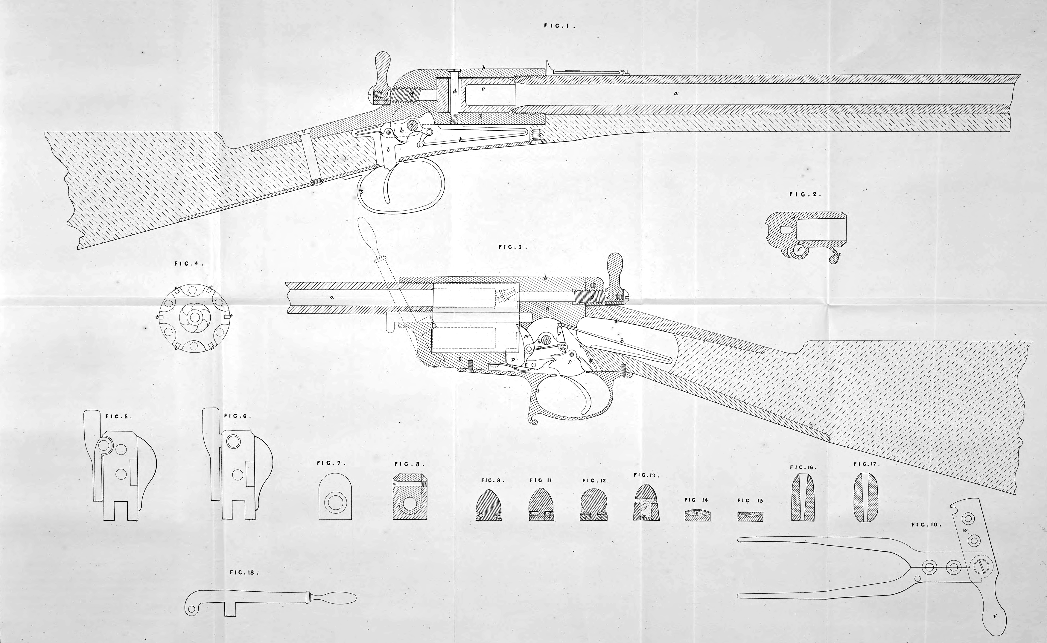
In order, however, that my Invention may be fully understood and readily carried into effect, I will proceed to describe the accompanying Drawings. Fig. 1 is a longitudinal section of part of a gun, with the plug or stopper above referred to applied thereto; Fig. 2 is a horizontal section of the plug or stopper detached ; Fig. 3 is a longitudinal section of part of a gun, with a revolving chamber combined with the lock above referred to applied thereto; Fig. 4 is an end view of the revolving chamber.
In each of these Figures the same letters of reference indicate corresponding parts, a, Fig. 1, is the barrel of the gun; b, the ordinary solid frame (with a solid top strap) within which the plug or stopper c is placed or fitted, so as to be capable of turning horizontally on the vertical pivot d, the required distance for loading. This pivot is a pin screwed into the frame b, as shewn in the Figure, or it may be fitted into the plug without screwing, and move in a slot in the top strap and the bottom strap. The plug or stopper c is represented as formed in one piece, but it may be formed in two pieces united by their mutual connection with the pivot d. The end of the plug or stopper next the barrel is fitted to the end of the latter so as to form a conical junction between them, but the two ends may be formed so as to produce a flat or straight junction e. Fig. 2 is a projecting lip on the side of the plug or stopper c, by which the latter may be turned on the pivot d, as required. The situation of the nipple or the tube, whichever may be employed, with the communication of the same with the interior of the plug or stopper, is shewn at /, in Fig. 2. g is the set screw by means of which the plug or stopper is to be set against the end of the barrel. The bolt or pin on the end of the screw g fits into a cavity formed in the back of the plug or stopper c, so as to admit of the latter being moved on the pivot d. The set screw g is turned, in order to set forward the plug or stopper, by a finger piece on its outer end as shewn, h is the tumbler, fixed on the same centre of motion f, with the ordinary cock, which is only indicated by dotted lines in the Figure. One end of the tumbler h is connected by a link j to the main spring k, by which spring, connected with the tumbler h, the cock is projected on to the nipple or tube on the drawing back of the trigger l. This gun with its plug or stopper might be combined with a lock of a different construction from that shewn, which is a lock fitted to the middle of the frame of the gun, and is covered on one side by a shield, the frame itself forming the covering on the other side. The plug or stopper may also be combined with the gun or guns described in the Specification of a Patent granted unto me, and bearing date January Twenty-eighth, One thousand eight hundred and fifty-three. 'The action of the plug or stopper is as follows:—By pressing against the projecting lip e, the plug or stopper is turned horizontally on the pivot d, a sufficient distance to admit of the charge being inserted therein, after which it is returned by the same means to its original position, when the piece may be discharged by drawing the trigger in the usual way.
In Fig. 3, c is an ordinary revolving chamber turning as usual on the horizontal pivot or axle d, and set forward against the end of the barrel a, by the set screw g. This chamber is bored taper-formed, or conical about half a degree, and the lubricated bullets herein-after described are fixed in it by the loading lever herein-after referred to. In this chamber the revolving chamber c is combined with the lock now to be described, which is a lock fitted into the middle of the frame of the gun, and covered on one side by a shield and bridle, as represented in Figs. 5 and 6, the other side being covered by the frame. At Figs. 7 and 8 are shewn detached, in cross section, two modifications in the form of top strap that may be used. The lock now to be described is fitted with a tumbler h, turning on the centre i, on which the cock also turns, which tumbler is connected by the link j to the main spring k; m is a lifter jointed to the reverse end of the tumbler K This lifter is kept within the ratchet tooth on the end of the chamber c, by the spring n, and is withdrawn therefrom by the stud o, on the stop piece p, acting against the lower end of the lifter. The trigger l is also pressed forward as shewn by the small spring q, and the stop piece p by the spring r. The ordinary guard is shewn at s. By means of this arrangement of the parts the chamber c is actuated in the ordinary manner by raising the cock, thereby turning the tumbler A, and raising the lifter m, so as to cause its upper end to press against the ratchet on the chamber, into one of the teeth of which it is passed. When the chamber has been thereby turned a sufficient distance, the upper part of the stop piece p passes into one of the notches t of the chamber, shewn at Fig. 4, and retains the chamber. This is effected by drawing the trigger l, and the tumbler h will at the same time be acted upon by the main spring k, and the cock projected upon the nipple.
Fig. 9 represents, in section, a bullet formed with a groove round it near the base, which groove is intended to be filled with grease of any suitable kind. By the pressure exerted against the base of this bullet on the explosion of the charge of powder, it will yield and cause the grease to be pressed out into the barrel of the gun or pistol. Fig. 10 shews on a reduced scale a mould for casting these bullets and forming the base flat. After the lead has been poured into the mould, the cover u, being suddenly raised by a blow on the tail r, will cut off the base of the bullets flat. Fig. 11 is a section of a bullet, with a projection at the bottom, over which is placed a wadding w, leaving a space for the grease which will become pressed out by the pressure of the exploding powder upon the wadding; Fig. 12 shews a modification of this bullet. Fig. 13, is a section of a bullet formed with a hollow space in the interior for receiving the grease, and having a plug x, to close the aperture, the pressure upon the plug forcing it into the cavity, and thereby discharging the grease.
Figs. 14 and 15 represent different forms of waddings containing grease as at y, the grease being covered by a thin substance easily broken, and allowing the grease to become discharged.
Figs. 16 and 17 are sections of two different forms of bullets with internal cavities with inclined sides, thereby forming conical apertures, with the larger diameter in the front part of the bullets. Fig. 18 represents a moveable lever which is required to be put upon a stud in the frame of the gun, and worked therefrom as a ram rod, to force bullets of this description into the loading chambers. It is shewn at Fig. 3, by dotted lines in the position which it would occupy when applied to the stud or fulcrum on the frame.
Having thus described the nature of my Invention, and in what manner the same is to be performed, I would have it understood that I do not mean or intend to confine myself to the precise forms and arrangements of the parts shewn and described. But what I claim as of my Invention is,—
First, the plug or stopper c, in its general features and applications to fire-arms, as described.
Secondly, the combination of the lock represented at Fig. 3, and described, with the revolving chamber as described.
Thirdly, the several modes described of forming and constructing bullets and waddings so as to admit of grease being readily discharged therefrom on the explosion of the powder.
And lastly, the formation of bullets with a hole through them in the centre.
In witness whereof, I, the said William Tranter, have hereunto set my hand and seal, this Twelfth day of June, in the year of our Lord One thousand eight hundred and fifty-four.
(l.s.) william tranter.
Witnessed by
B. Najs’Carrow.