
British 1913
LETTERS PATENT to William Tranter, of Birmingham, in the County of Warwick, Gun Maker, for the Invention of “Improvements in Fire-arms.”
Sealed the 5th December 1856, and dated the 16th August 1856.
PROVISIONAL SPECIFICATION left by the said William Tranter, at the Office of the Commissioners of Patents, with his Petition, on the 16th August 1856.
I, William Tranter, of Birmingham, in the County of Warwick, Gun Maker, do hereby declare the nature of the said Invention for “ Improvements in Fire-arms,” to be as follows:—
My Invention consists in adapting and applying to revolving fire-arms the several kinds of single-action locks herein-after described; also the several kinds of double-action and treble-action locks herein-after described; also the method of arranging such locks in the fire-arm, by turning out the cavity in the body or frame for the works by means of a lathe, as herein-after described 5 also the several kinds or combinations of levers or mechanism for forcing the bullets into the chambers of revolving fire-arms, herein-after described.
The first part of my Invention may be described as follows :—The cock or hammer will be raised by the thumb of the right hand, and may be placed in the middle or on the side of the fire-arm; when on the side, a tumbler must be used in connection therewith. The lifter for turning the chamber is intended to be placed in the cock or tumbler, or in a lever acting in connection with the cock. The trigger may be placed before or behind the cock or tumbler. The stop for the chamber may be made in connection with a lever or trigger, or with both, or working in connection either with the cock and trigger, or with a lever and the cock.
The second part of my Invention may be described as follows :—The cock or hammer may be placed in the middle of the body or frame, or on the side thereof, and may be lifted either directly by the thumb, or by the finger pressing against the trigger; when lifted by the thumb it is discharged as in an ordinary pistol, but when lifted by the trigger it is discharged as soon as lifted. In order to effect the above movements, the catch moving in the trigger is formed with a kind of hook at its upper end to act on a suitable projection on the cock. The cock or tumbler is formed with bents or notches as an ordinary cock or tumbler. Another kind of catch is made to fall into the said bents or notches similar to that for the double trigger, described in the Specification of my Patent bearing date 28th January 1853, but pinned in the body or frame instead of in the trigger, the trigger acting against the catch to discharge the piece. The catch may also bo attached to the cock instead of to the trigger, and may be differently shaped for working in connection with the trigger instead of with the cock. Another description of catch may be attached to the trigger, which would discharge the piece by moving towards the pin on which the cock moves instead of from it, as with the double trigger before referred to.
The third part of my Invention may be described as follows:—The cock or hammer may be raised either directly by the thumb, or by means of the double trigger in my former Patent, and acting in connection with the catch above described placed in the body or frame, in addition to the catch acting in the double trigger. The catch pinned in the body or frame may be made to act either in connection with the cock or with the double trigger, and may be acted upon by either of the triggers forming the double trigger. The cavity in the body or frame, in which the works are intended to move, may be turned out by means of a lathe, instead of by the usual method of chipping and filing. For this purpose the body or frame is fixed upon a plate, and the cavity turned out in the usual mode of turning.
The last part of my Invention consists of a lever placed on either side of the body or barrel, but in either case near the top square of the barrel, and connected with a forcer for the bullets by means of a swivel pin or slot, or by a combination thereof.
SPECIFICATION in pursuance of the conditions of the Letters Patent, filed by the said William Tranter in the Great Seal Patent Office on the 16th February 1857.
TO ALL TO WHOM THESE PRESENTS SHALL COME, I, William Trakter, of Birmingham, in the County of Warwick, Gun Maker, send greeting.
WHEREAS Her most Excellent Majesty Queen Victoria, by Her Letters Patent, bearing date the Sixteenth day of August, in the year of our Lord One thousand eight hundred and fifty-six, in the twentieth year of Her reign* did, for Herself, Her heirs and successors, give and grant unto me, the said William Tranter, Her special license that I, the said William Tranter, my executors, administrators, and assigns, or such others as I, the said William Tranter, my executors, administrators, and assigns, should at any time agree with, and no others, from time to time and at all times thereafter during the term therein expressed, should and lawfully might make, use, exercise, and vend, within the United Kingdom of Great Britain and Ireland, the Channel Islands, and Isle of Man, an Invention for “ Improvements in Fire-arms,” upon, the condition (amongst others) that I, the said William Tranter, by an instrument in writing under my hand and seal, should particularly describe and ascertain the nature of the said Invention, and in what manner the same was to be performed, and cause the same to be filed in the Great Seal Patent Office within six calendar months next and immediately after the date of the said Letters Patent.
NOW KNOW YE, that I, the said William Tranter, do hereby declare the nature of my said Invention, and in what manner the same is to be performed, to be particularly described and ascertained in and by the following statement; reference being had to the Drawings hereunto annexed, and to the letters and figures marked thereon (that is to say) :—
My Invention of “ Improvements in Fire-arms ” consists in adapting and applying to revolving fire-arms the several kinds of single-action locks hereinafter described; also the several kinds of double-action and treble-action locks herein-after described; also the method of arranging such locks in the fire-arm, by turning out the cavity in the body or frame for the works by means, of a lathe, as herein-after described; also the several kinds or combinations of levers or mechanism for forcing the bullets into the chambers of revolving fire-arms, herein-after described.
The first part of my Invention may be described as follows :=—The cock or hammer will be raised by the thumb of the right hand, and may be placed in the middle or on the side of the fire-arm; when on the side, a tumbler must be used in combination therewith. The lifter for turning the chamber is intended to be placed in the cock or tumbler, or in a lever in connection with the cock. The trigger may be placed before or behind the cock or tumbler. The stop for the chamber may be made in connection with a lever or trigger, or with both, or working in connection either with the cock and trigger, or with a lever and the cock.
The second part of my Invention may be described as follows:—The cock or hammer may be placed in the middle of the body or frame, or on the side thereof, and may be lifted either directly by the thumb, or by the fingbr pressing against the trigger; when lifted by the thumb it is discharged as in to ordinary pistol, but when lifted by the trigger it is discharged as soon as lifted. In order to effect the above movements, the catch moving in the trigger fe formed with a kind of hook at its upper end to act on a suitable projection oil the cock. The cock or tumbler is formed with bents or notches as an ordinary cock or tumbler. Another kind of catch is made to fall into the said bents or notches similar to that for the double trigger, described in the Specification of my Patent bearing date Twenty-eighth January, One thousand eight hundred and fifty-three, but pinned in the body or frame instead of in the trigger, the trigger acting against the catch to discharge the piece. The catch may also be attached to the cock instead of to the trigger, and may be differently shaped for working in connection with the trigger instead of with the cock. Another description of catch may be attached to the trigger, which would discharge the piece by moving towards the pin on which the cock moves instead of from it, as with the double trigger before referred to.
The third part of my Invention may be described as follows:—The cock or hammer may be raised either directly by the thumb or by means of the double trigger in my former Patent, and acting in connection with the catch above described, placed in the body or frame in addition to the catch acting in the double trigger. The catch pinned in the body or frame may be made to act either in connection with the cock or with the double trigger, and may be acted upon by either of the triggers forming the double trigger. The cavity in the body or frame, in which the works are intended to move, maybe turned out by means of a lathe, instead of by the usual method of chipping and filing. For this purpose, the body or frame is fixed upon a plate, and the cavity turned out in the usual mode of turning. –
The last part of my Invention consists of a lever, placed on either side of the body or barrel, but in either case near the top square of the barrel, and connected with a forcer for the bullets by means of a swivel pin or slot, or by a combination thereof.
In order, however, that my Invention may be fully understood, I will proceed to describe it more particularly by the aid of the accompanying Drawings, in which are represented the improvements above referred to as applied to pistols, but they may be applied to other fire-arms.
Description of Drawings.
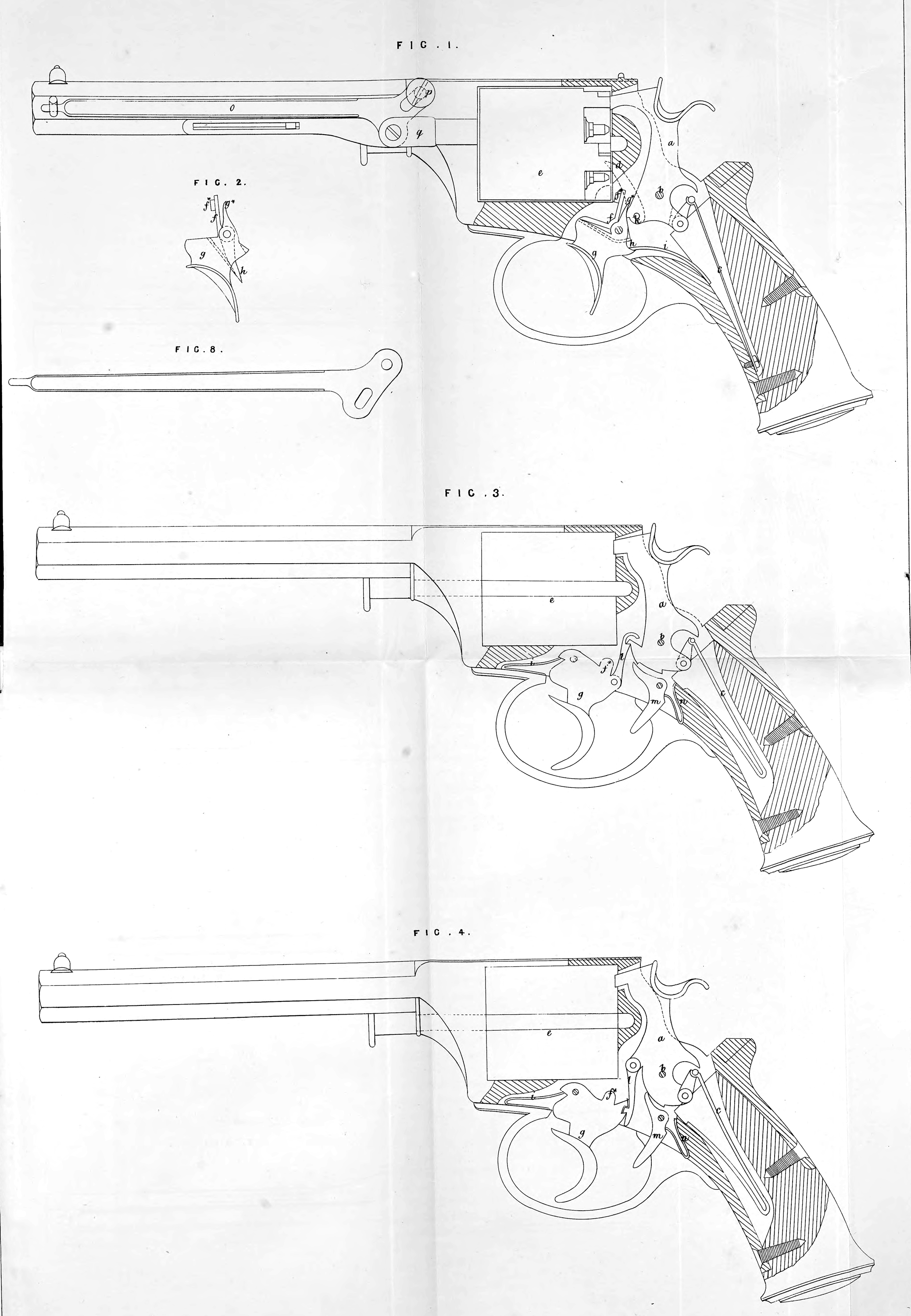
Fig. 1 is a side elevation of a pistol, with a lock applied of the construction referred to under the first head of my Invention ; the stock of the fire-arm being shewn in section, in order to admit of the working parts of the lock being shewn more evidently; Fig. 2 is an elevation of a trigger with a modified form of stop lever for locking the loading chamber ; Figures 3, 4, and 5 represent portions of a pistol, with locks applied of the construction referred to under the second head of my Invention; Figures 6 and 7 represent the same, with locks of the construction referred to under the third head of my Invention. In all these several Figures the same letters of reference indicate corresponding parts.
a (Fig. 1) is the cock or hammer; 6 is its pivot or centre of motion, fixed in the frame of the fire-arm ; c is the ordinary spring for throwing it upon the nipple when discharged. The cock or hammer a is in this case shewn in the middle of the fire-arm. d is the lifter for turning the ordinary loading chamber e, such lifter being connected to the cock or hammer as shewn; / is a stop lever connected to the trigger g, having a stop /* or projection for the purpose of locking the chamber e when required, by passing into one of the slots at the end of the chamber. At the back of this stop lever / is a tail piece h, which is acted upon by a spring fixed to the trigger in such a manner as to press the end of the lever with the stop /* towards the end of the chamber, and cause the stop /* to pass into the respective slot as required when the trigger has been drawn back sufficiently for the purpose, i is a spring fixed to the frame so as to press on the back of the trigger and cause its upper end g* to pass into a bent or notch h in the cock or hammer, and retain the latter after it has been raised by the thumb.
The action of this fire-arm is as follows:—On the cock or hammer a being raised, the lifter d will be made to turn the chamber e a sufficient distance to bring the required slot in suitable position in front of the stop f*; the upper part g* of the trigger will have passed into the notch 1c, so as to hold the cock or hammer; then, by drawing back the trigger g, the stop/* will be projected into the slot of the chamber to lock it, and the upper part g* of the trigger will be withdrawn from the notch 1c, when the cock or hammer will be discharged by the main spring c upon the nipple. The chamber is released from the stop/*, after the discharge, by the upper part of the trigger being carried back by the pressure of the spring i on the back of the trigger, the cock or hammer being formed so as to admit of such part of the trigger retreating a sufficient distance for the purpose. At Fig. 2 it will be seen that the form of the stop lever / is modified, its mode of action being similar.
In Fig. 3, l is a hooked catch, the hook of which fits on to a projection on the cock or hammer a. In this case also the cock or hammer has bents or notches into which the catch m is made to pass when the cock is raised; this catch m is pinned into the frame, and has a spring n pressing upon the back of it to cause it to pass into the bent or notch of the cock; the spring t keeps the hooked catch l in contact with the cock or hammer by pressing against the front of the trigger, as shewn; /* is the stop for the chamber, being a projection on the trigger; the lifter for the chamber is not shewn. The cock or hammer, having been raised by the thumb, is discharged by drawing back the trigger, so as to withdraw the catch m from the bent or notch of the cock or hammer, hy bringing the trigger against the lower arm of the said catch m, the hooked catch l being, by the same motion of the trigger, raised out of contact with the projection on the cock or hammer. The catch m may, if preferred, be formed with a hook at its lower end, to form a connection with the trigger, so as to dispense with the bents or notches in the cock or hammer.
In Fig. 4, the catch l is shewn connected to the cock or hammer, instead of to the trigger, as in Fig. 3, and formed with a projection fitting into a notch on the back of the trigger. By this means the cock or hammer may be raised either by the thumb or by the trigger, and it is discharged by withdrawing the catch out of the bent or notch in the same manner as in the former case.
In Fig. 5, the hooked catch l is so formed and adapted to the projection on the cock or hammer as to move towards the pivot 6, when* the trigger is drawn back to discharge the fire-arm, instead of away from it, as in the case of Fig. 3; the action of the parts being otherwise similar to that in the two instances just described.
In Fig. 6, the catch l is connected to the back of the trigger g, and its upper end passes into a circular notch iu the front of the cock or hammer. By this means the cock or hammer may be raised either by tho thumb or by the trigger, when the end of the catch m will be passed into tho notch at the back of the trigger g, and this catch m may be drawn out of the said bent or notch by the trigger gx coming in contact with it; at the same time the said trigger g1 is made to press against the tail piece of the catch Z, and in this manner the cock or hammer is liberated, so as to be discharged by the spring c on to the nipple. If preferred, the catch m may be made to fall into bents or notches in
the cock or hammer, as at Fig. 3.
In Fig, 7 the parts are similar to those in Fig. 6, except that the fire-arm is capable of the treble action of having the cock raised by the thumb, or by the trigger g, and discharged by the trigger g\ being brought in contact with the lower end of the catch m and the tail piece of the catch Z, or the cock may be raised and discharged by the trigger g\
At Fig. 1 is represented my improved lever for loading the chambers, o is the lever, acting on a pivot or fulcrum p; to this lever is jointed the plunger or loader q, to the back of which is fitted a guide with a slot in it working over a stud fixed in the barrel of the pistol; there is also a slot in the end of the lever o to admit of the parallel movement of the plunger or loader q.
Fig. 8 represents the lever with a slot formed in the part thereof connected with the plunger or loader q, instead of in the part shewn at Fig. 1.
Having thus described the nature of my Invention, and in what manner the same is to be performed, I would remark that I do not mean or intend to confine myself to the precise forms and arrangements of the parts of fire-arms represented and described, neither do I claim, as of my Invention, any of the parts herein-before described separately, or otherwise than as herein-after stated; but I do claim as of my Invention,—
First, the combination of the parts, described under the first head of my Invention, having reference to single action locks, or those in which the cock or hammer is raised by the thumb and the fire-arm discharged by the trigger, in the manner described.
Secondly, the combination of the parts of fire-arms, described under the second head of my Invention, -having reference to double-action locks, or those in which the cock or hammer may be raised either by the thumb or by means of the trigger, and the fire-arm discharged by the trigger acting on a catch, in
the manner described.
Thirdly, the combination of the parts of fire-arms, described under the third head of my Invention, having reference to those locks in which the cock or hammer may be raised either by the thumb or by means of a double trigger or pair of triggers, and the fire-arm discharged by the action of the discharging part of the double trigger, or the discharging trigger of the pair of triggers on the catch, in the manner described.
Fourthly, the turning out, by means of a lathe, of the cavity in the body or frame, for the insertion of the working parts of the fire-arm.
And, lastly, the adaptation and application of the particular form of loading lever described.
In witness whereof, I, the said William Tranter, have hereunto set my hand and seal, the Fourteenth day of February, in the year of our Lord One thousand eight hundred and fifty-seven.
WILLIAM TRANTER. (l.s.)
Witness,
William Spence,
60, Chancery Lane.