
US 33382
UNITED STATES PATENT OFFICE.
WM. H. ELLIOT, OF PLATTSBURG, NEW YORK.
IMPROVEMENT IN REVOLVING FIRE-ARMS.
Specification forming part of Letters Patent No. 33,382, dated October 1, 1861.
To all whom it may concern:
Beit known that I, Wm. H. Elliot, of Plattsburg, in the county of Clinton, in the State of New York, have invented a new and Improved Repeating Pocket-Pistol; and I do hereby declare that the following is a full and exact description thereof, reference being had to the accompanying drawings, and to the letters of reference marked thereon.
Similar letters of reference indicate the same devices in all the figures.
To enable others skilled in the arts to comprehend, make, and use my invention, I will proceed to describe its nature, construction, and operation.
The nature of my invention consists in a novel method of employing, combining, and arranging certain devices, by which a compact and convenient pocket-pistol is obtained.
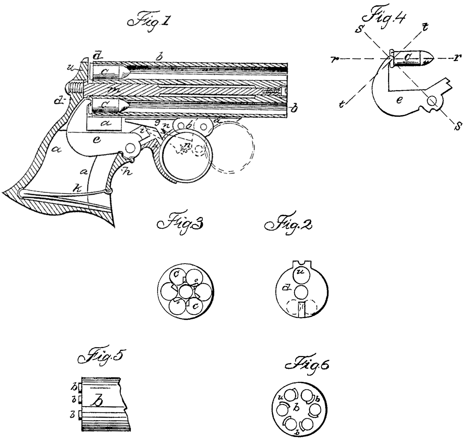
Figure 1 is a perpendicular section of my pistol, showing the lock in elevation. Fig. 2 is an elevation of a breech-plate. Fig. 3 is an elevation of the end of a series of barrels, showing the chambers filled with exploded cartridges. Fig. 4 is an elevation of a hammer and cartridge, with dotted lines showing the direction of certain forces at the moment of the discharge. Fig. 5 is an elevation of the rear end of a barrel, showing the projections or anvils. Fig. 6 is the same as Fig. 5.
a is the frame; b, barrels, bored through at their rear end for the purpose of being charged at the breech; c, cartridges; d, breech-plate; e, hammer, pivoted underneath and forward of the rear end of the barrels; f, trigger; g, cocking-pawl; h, stirrup; i, notch upon the hammer into which cocking-pawl g falls; k, mainspring; m, base-pin; n, set-screw between the hammer and trigger; o, impression made by the point of the hammer upon the shell of the cartridge; r and r’, line showing the direction of the recoil; s and s’, direction of the resistance offered by the hammer; t, plane of the surface acted upon by the hammer; u, opening through the breech-plate for passing the cartridge into the chambers; v, projections or anvils.
This pistol is loaded bypassing the cartridges through opening u in the breech-plate into the chambers, and to fire it the trigger must first be pushed forward to the position represented by the dotted lines, Fig. 1, when the rear end of pawl g falls into notch i upon the hammer, and as the trigger is carried backward again the hammer is raised until the side of the trigger comes in contact with the head of screw n in pawl g, by which means, the rear end of pawl g is raised out of notch i and the hammer falls upon the cartridge and explodes it. When it becomes necessary to pass the trigger back without firing, it may be done by pressing upon the lower side of the cocking-pawl, when its rear end will be raised out of the notch in the hammer, in which position the trigger may be carried back without raising the hammer.
It may be seen by reference to the drawings that the hammer is pivoted underneath and forward of the rear end of the barrels or chambers, and also forward of the breech-plate, and when the hammer is raised or cocked for the purpose of firing its free end passes down into the handle of the pistol within the hand; and upon being snapped the exploding-point falls in an oblique direction upon the cartridge, penetrating a little into the copper shell. A hammer so arranged in relation to the chambers holds onto the cartridge like a hook at the moment the discharge takes place, and thus prevents the full recoil of the cartridge against the breech-plate, the effect of which is to relieve the breech-plate of the pressure of the shells of the cartridges and the consequent friction when the barrels are revolved. The cartridges are passed into the chambers, as shown in Fig. 1, through opening u in the breech-plate, and the recoil is parallel with the bore of the barrel, or, as represented in Fig. 4, from r to r’, the resistance of the hammer to the recoil of the cartridge being in the direction of s to s’. The exploding-point by the force of the blow is embedded into the copper shell, and thus produces a surface upon which it holds, the plane of which is in t t, exactly at right angles to the line of resistance offered by the hammer. Thus it may be seen that the hammer, even without the assistance of the mainspring, would not slip down upon the head of the cartridge. Numerous experiments have proven that either with or without a breech-plate the point of the hammer is never displaced by the recoil of the cartridge.
The employment of a hammer arranged as shown in the drawings, and as hereinbefore specified, in relation to the barrels or frame, with chambers bored through and left open at their rear end, and with a breech-plate, is an important improvement, as a degree of compactness is obtained by this combination that could not possibly be had without it.
The projections v on the rear end of the barrels serve as anvils, between which and the exploding-point of the hammer the rim of the cartridge is crushed. This projection is a slight elongation of the barrel or chamber, arranged upon the side upon which the point or face of the hammer strikes and directly under said point, the purpose of which is to provide for any irregularity in the construction of the cartridge, so that the rim of the cartridge may always find a firm resting-place at the side of the chamber under the exploding point of the hammer.
Screw in in the cocking-pawl is for the purpose of regulating the action of the trigger, so as to determine the exact point at which it shall raise the pawl g so as to disengage the hammer. This is an important improvement, as a slight wearing of the joints of the trigger and pawl would derange their operations and render them useless if no intervening device were employed for regulating them.
One striking peculiarity of this invention consists in the arrangement of the different parts of the frame in relation to each other, by which a more compact pistol is obtained than could be had without it— viz., the arrangement of the breech-plate in the rear of that portion of the frame to which the hammer is pivoted. By “breech-plate” I mean that portion of the pistol (marked d) against which the cartridge recoils, and which is detached from both the hammer and chamber. This breech-plate serves the purpose of a breech-pin to the barrels, and can only be employed with chambers that are bored through and left open for the purpose of being charged at the rear end.
Having described my invention, what I claim, and wish to have secured to me by Letters Patent, is—
1. Extending the frame a forward of the breech-plated and hanging in the part so extended forward the hammer e and trigger f, when these devices are employed with chambers that are bored through and left open for the purpose of being charged at the rear end, as and for the purpose specified.
2. The employment of set-screw n between the cocking-pawl g and trigger f, when said to determine at what point in the motion of the trigger the hammer shall be disengaged, as set forth.
3. Resisting the recoil of the cartridge by means of a hammer pivoted underneath and forward of the rear end of the chambers, as set forth.
5. The employment of a hammer so arranged in relation to the chambers that while it is pivoted underneath and forward of the rear end of said chambers its exploding-point strikes up in their rear, as specified.
Ilion, Herkimer county, New York,8th June, 1860.
WM. H. ELLIOT.
Witnesses:
I. Harrington,
W. W. Thomas.