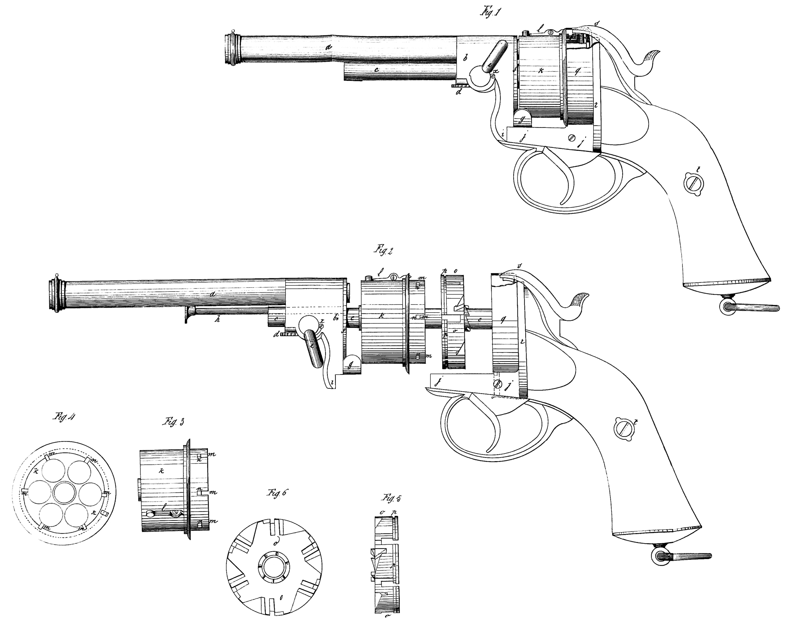
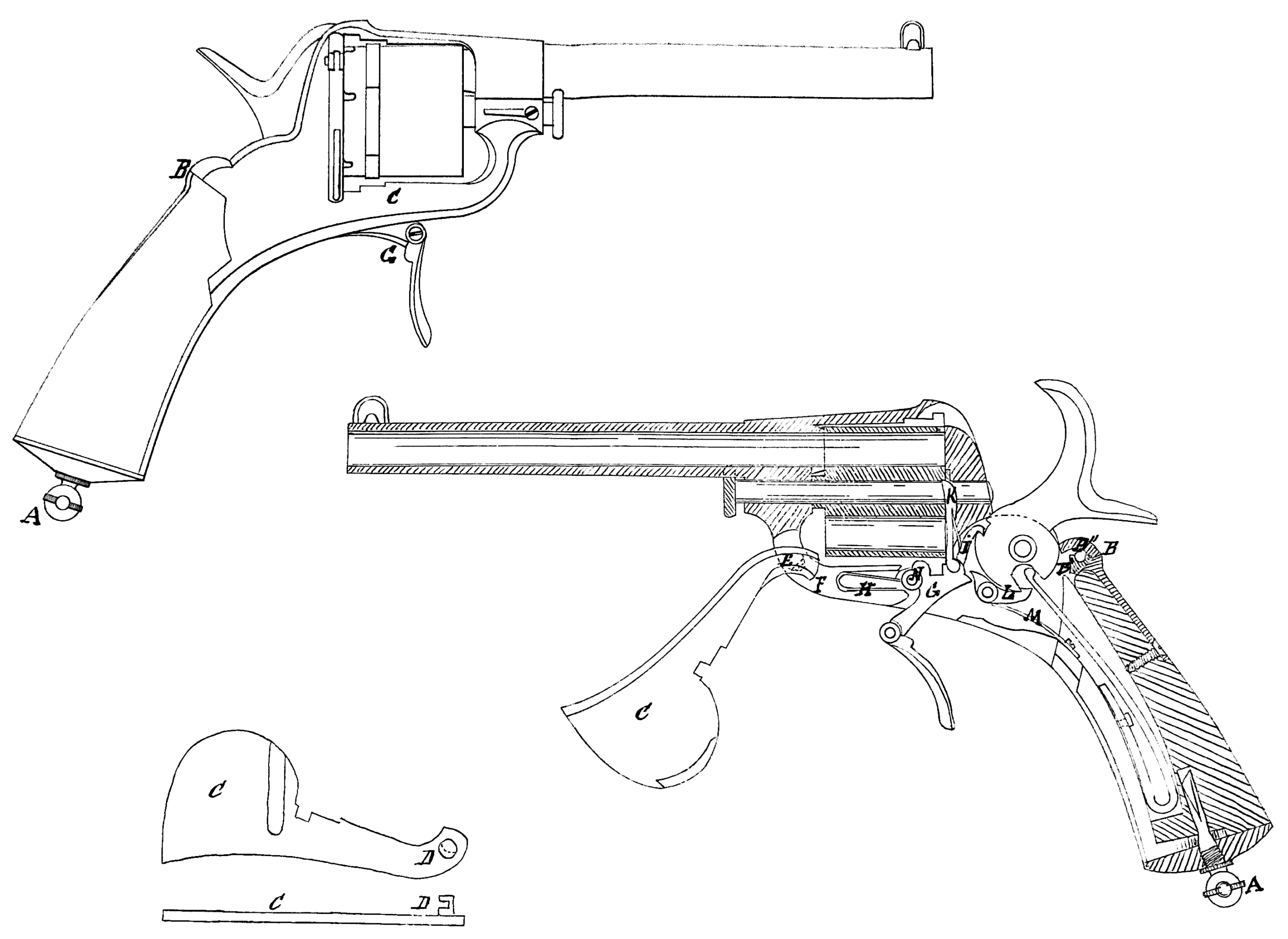
Britain 20321

№ 20,321 A.D. 1889

Date of Application, 18th Dec., 1889

Complete Specification Left, 13th Feb., 1890—Accepted, 3rd May, 1890

PROVISIONAL SPECIFICATION.

Improvements in Revolvers and other Breech-loading Small-arms

I, Edwinson Charles Green, Gun & Revolver Maker, 87 High Street, Cheltenham, Gloucestershire, do hereby declare the nature of this invention to be as follows:—

My invention for improvements in breech-loading revolvers refers to an improved lock mechanism, also a method of securely bolting the barrel & breech action of same, also a method for preventing the fouling of the cylinders of revolvers, also a plan for lightening revolver & rifle barrels, also to covering the handles of revolvers with cork or similar material.

To securely lock the barrels & body together of what are known as drop-down revolves,”which are fitted with a dove-tailed top projection breech support,”— I one on each side — corresponding recesses are cut in the rear sides of the revolver frame, a pin is fitted through the lever link fastening & the frame to hold it in position.

On the upper part of the lever link is formed a projection, which when the hammer is down is made to abut on or over the top or head of the revolver hammer, so that until the hammer is half cocked, the breech cannot be opened.

Or, instead of the foregoing, a projecting stud can be left on the head of the hammer, and a corresponding recess for it formed in the head of the link lever fastening, or a stud can be formed on the lever link fastening, & a corresponding hole for its reception formed in the head of the hammer.

This form of lever link support can also be made on revolvers fitted with rebounding locks, but when so preferred, I use that form of double-action half. cocking lock which cannot rebound while the trigger is held back; the revolver can only be fired by the head of the hammer passing underneath the top bar of the lever link, thereby more securely locking the revolver during each discharge than can be done when the lever is not supported by the hammer, but so soon as the trigger is released the hammer rebounds, & the breech is left free to be opened.

To open with one motion my revolver with an ordinary lock, mount on the pin on the link fastening a suitable thumb-piece, & upon its being pressed down, the upper or link part is drawn back, & the barrel left free to be opened at the breech. In either case this lever link fastening can be made self-closing by the aid of a spring, or the spring can be dispensed with.

For the lock-work of what are known as hammerless revolvers, I mount in the head of the revolver, a revolving striker head, shaped with suitable grooves, & fitted with a guide actuated in the customary manner by a spring and trigger. In front of the striker head, & in connection with it, a ratchet or stud formed collar head is carried through the face of the action, & is made io engage in or against suitable recesses formed on the rear of the cylinder, so that when the lock is cocked, the cylinder is made to rotate by the studded collar, & held in position during the firing of the cartridge.

I make this lock a double-action one by the aid of a sear & an outside cocking arm, on which the tumbler of the lock is mounted, & by the aid of a suitable rod, one end being mounted underneath & against the main spring, & the other carried forward to the trigger or cylinder lifter, enables me to dispense with a separate sear or trigger spring, & I make the lock rebounding ,by the aid of a separate spring acting upon the trigger or striker head, or hy the aid of the mainspring acting upon either, or a separate arm, or by lengthening the lower part of the mainspring, so as to make it rest on the trigger or its lifter, the trigger both rod & sear spring can be dispensed with. Upon the outside cocking lever being pulled; the mainspring is compressed, bringing the lock to fall cock, or by pulling the trigger only, the lock is full cocked, & carried beyond its turn, & so forces the inside rotating striker-head forward to deliver its blow-on the-cartridge, & at the same time hold in position either the link or bolt, of the breech fastening.

Or, instead of the foregoing form of breech fastening, I fit in a hole which I form in the head of the frame, & against the top projection of the frame, also through the rear-of the barrel projection,*either an oblique or a vertical bolt, capable of motion. This holt is made self-acting by the aid of a spring. A projecting thumb piece is formed on the side of this bolt, or a separate thumb lever can be fitted to operate it, & when preferred a sliding self-acting stop is fitted to lock the vertical or oblique bolt, & prevent it being withdrawn until the slide is pushed back.

The barrel of the revolver is hinged to the forward part of the frame in the customary manner, & upon pressing down the thumb-piece of t re bolt, the barrel & cylinder can be tilted & made free for loading, or ejecting the discharged cartridge cases; upon closing the breech, the bolt is forced upwards by the spring in the hole formed in the rear of the barrel projection,-thereby securely locking the barrel and frame together.

The hammer is conveniently arranged in connection with the bolt so that it is impossible to fire the revolver unless the bolt is in its secure position, also when preferred, I fit a stop catch to keep the bolt down when the revolver is open for loading.

l make the revolver so that it can be cocked in the customary manner by the trigger, also by the hammer in the centre of the frame, or by a lever mounted on the side of the revolver.

By this latter plan, the lock mechanism is better preserved from the effects of out-side fouling.

To prevent the cylinder of my revolver from becoming foul or difficult to rotate after firing, I shape the central forward end of the cylinder where it is mounted on the centre rod, either concave or inclined.

As an additional precaution, I also form on the centre rod spiral grooves, & drill one or more holes in the base of the barrel, whereby at the moment of discharge the gas, & residuum of the cartridge may be deflected, & the fouling of the revolver avoided.

As a further protection to the efficient: use of my revolver from the insidious effects of sand & dust, I fit a leather or metal cover over the cylinder & barrel, which when preferred can be retained on the’ revolver during the act of firing.

When it is desirable to make revolver or rifle barrels light, & retain their maximum amount of strength, I form the outsides in a poly groove shape.

With the object of giving a firm grip to my revolver, & prevent its slipping in the hand when being fired, I fit on the handle a covering of cork or similar material.

Dated this 16th day of December 1859.

EDWINSON CHARLES GREEN.

COMPLETE SPECIFICATION.

Improvements in Revolvers and other Breech-loading Small-arms.

I, Edwinson Charles Green, Gun & Revolver Maker, 87 High Street, Cheltenham, Gloucestershire do hereby declare the nature of my invention for Improvements in Revolvers and other Breech-loading Small-arms and in what manner the same is to be performed, to be particularly described and ascertained in and by the following statement:—

My invention has reference to what are known as drop-down breech-loading hammer and hammerless revolvers, & consists of the arrangements or combination of parts as hereinafter described for-securely locking together the barrels and breech or frame of revolvers and pistols.

Also to a simple form of hammerless revolver lock.

Also to a method for preventing the cylinder from being fouled during the discharge of the said revolvers.

And to the use of cork on the handle of revolvers to give a firm grip to the user.

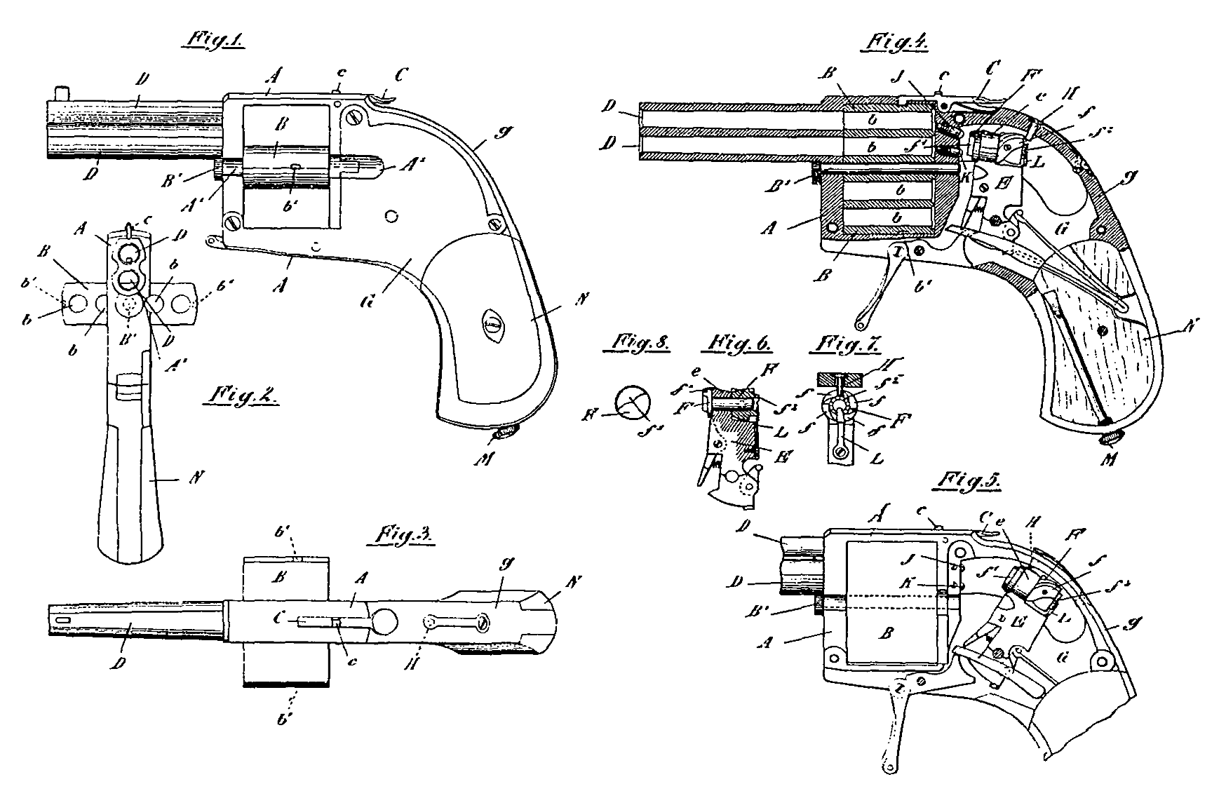
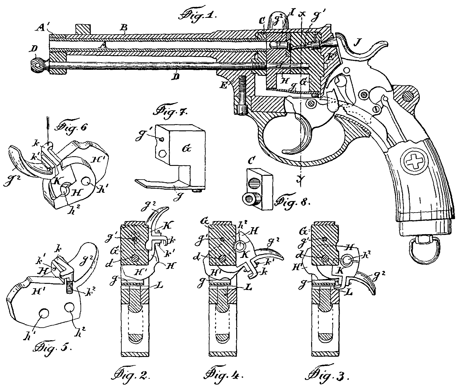
To securely lock the barrels and body together of what are known as drop-down revolvers, which are fitted with a dove-tailed top projection breech support, I form on the inside of the vertical part of my lever link fastening, two raised bosses, Fig. A 1-1; corresponding recesses are cut in the rear sides of the revolver frame, Fig. B & BˣX 2-2.

A pin is fitted through the lever link fastening & frame to hold it in position, Fig. A & B-3.

On the upper part of the lever link is formed a projection, Fig. A & B 4-4-4, which when the hammer is down is made to abut on or over the top or head of the revolver hammer 5, so that until the hammer is half or full cocked, the breech cannot be opened.

Or instead of the foregoing plan of lever link support, a projecting stud is formed on the head of the hammer 6, Fig. C, and a corresponding recess formed for it in the head or cross bar of the link lever fastening 7, or a stud can be formed on the lever link top bar D 8, and a hole formed for its reception in the head of the hammer, or a recess is formed underneath the lever link, Fig. B 8, into which the head of the hammer engages before the revolver can be fired.

These forms of lever link supports can also be fitted on revolvers which are provided with rebounding locks, bat when so preferred, I use that form of half-cocking lock which cannot rebound while the trigger is held back, similar to the lock arrangement shown in Fig. B. The revolver can only be fired after the head of the hammer has passed underneath the top bar of the lever link— and acting as a support of locking arrangement thereto— thereby more securely locking the revolver during each discharge than can be done when the lever is not supported by the hammer; as soon, however as the trigger is released the hammer rebounds, & the breech is left free to be opened.

To open with one motion my revolver with an ordinary lock (not rebounder) I mount on the pin, 3, of the link fastening a suitable thumb-piece Fig. D 9, & upon its being pressed down the upper or link part is drawn back & the barrel left free to be opened at the breech. In either case this lever link fastening can be made self-closing by the aid of a spring, or the spring can he dispensed with.

For the lockwork of what are known as hammerless revolvers, J mount in the frame of the revolver, a revolving centre-rod, operated by the hammer, shaped with suitable grooves, Fig. F 10, & fitted with a guide actuated in the customary manner by a spring and trigger. In front of the striker head and in connection with it, a ratchet or stud formed collar head, 11, is carried through the face of the action, & is made to engage in or against suitable recesses formed on the rear of the cylinder, so that when the lock is cocked, the cylinder is made to rotate by the studded collar, 11, & held in position during the firing of the cartridge. I make this revolver a double-action one by the aid of an outside cocking arm, 12, mounted on a tumbler hammer, In other respects the lockwork is of the customary revolver pattern.

Or instead of the foregoing A & B form of breech fastening, I fit in a hole formed in the head of the frame, & against the vertical top projection Fig. E 13, of the frame, also through the rear of the barrel projection, either an oblique or vertical bolt, capable of motion, Fig. E14. This holt is made self-acting by the aid of a spring, 15. A projecting thumb-piece is formed on the side of this bolt, 16, or a separate thumb-piece can be fitted to operate ii, also when preferred a sliding self-acting stop is fitted to lock the vertical or oblique bolt, & so prevent it being withdrawn until the slide is pushed back.

The barrel of the revolver is hinged to the forward part of the frame in the customary manner 18-18, & upon pressing down the thumb-piece 16— 16, of the bolt, the barrel & cylinder can be tilted, & made free for loading, or ejecting the dis-charged cartridge cases; upon closing the breech the bolt is forced upwards by the spring 15 into the hole formed in tie rear of the barrel top projection, thereby’ more securely locking the barrel & frame together, 19.

The hammer is conveniently arranged in connection with the bolt so that it is impossible to fire the revolver unless the bolt is in its secure position; also when preferred, I fit a stop catch to keep the bolt down when the revolver is open for loading.

I make the revolver so that it can be cocked in the customary manner by the trigger, also by the hammer, in the centre of the frame, or by a lever mounted on the side of the revolver; by this latter plan the lock mechanism is better preserved from the effects of outside fouling.

To prevent the cylinder of revolvers from becoming foul or difficult to rotate after firing, I shake the central forward end of the cylinder where it is mounted on the centre rod either concave or inclined, 20-20.

As an additional precaution, L also form on the centre rod spiral grooves, & drill one or more holes near the base of the barrel 21-21, whereby at the moment of dis-charge the gas and residuum of the cartridge may be deflected, & the fouling of the revolver avoided.

As a further protection to the efficient use of revolvers from the insidious effects of sand and dust I fit a leather or metal cover over the cylinder & barrel, which when preferred can be retained on the revolver during the act of firing.

When it is desirable to make revolver or rifle barrels light, & retain their maximum amount of strength, I form the outsides in a polygroove shape.

With the. object of giving a-firm grip to my revolver, & prevent its slipping in the hand when being fired, I fit on the handle a covering of cork or similar material.

Having thus particularly described and ascertained the nature of my said invention, I would have it understood that while I do not confine myself to the precise details herein before described, what I claim substantially as novel is

Firstly. The combination of the head of the hammer, or a projection thereon, passing underneath when down, and abutting against a part of the top bar of the lever link, or a projection thereon.

Secondly. The method by which— by the aid of the vertical bolt— the barrel and breech of revolvers are securely bolted.

Thirdly, A shell or covering of leather or metal to protect revolvers from becoming clogged by sand or dust.

Fourthly. The ratchet or stud-fronted grooved centre rod with the hammerless lockwork, combined for the purpose of revolving the cylinder.

Fifthly. Covering the handle of revolvers with cork.

In witness whereof, I the said Edwinson Charles Green have hereunto set my hand, February 12th 1890.

E. C. GREEN.

Britain 1923

A.D. 1886, 10th February. № 1923.

PROVISIONAL SPECIFICATION.

Improvements in Revolving Firearms.

I William John Whitting, of Whateley Road, Handsworth, in the County of Stafford, Toolmaker do hereby declare the nature of this invention to be as follows:—

The object of this invention is to prevent the fouling, which arises from the flash, from reaching the spindle upon which the cylinder of a revolver turns, as the eH’cct of the fouling on the spindle and cylinder is to retard and finally stop the revolution of the cylinder, and render the firearm unusable until it has been stripped.

My improvements consist in the addition of two short cylindrical guards or ferules, one overlapping the other, in such a way as to prevent the fouling from getting to the spindle.

To apply my improvements I cut sway a part of the lump under the barrel, so that the breech end of the barrel projects further back than the said lump.

Into this lump the hole for the cylinder spindle is bored in the ordinary way, but the upper part of the bore is enlarged. A ferule, having on it a raised collar, is then fitted into the enlarged portion of the bore, the collar being outside the bore. This ferule has a part, smaller than the raised collar, projecting backwards about as far as the rear end of the barrel.

This ferule is bored right through, and the spindle fits into and through it.

On the cylinder proper is another ferule, which fits easily over the reduced projecting part of the ferule affixed to the lump, forming a sleeve or guard over part of the first ferule. This cylinder ferule extends so far as nearly to touch the raised collar on the first ferule.

The result of this arrangement, is that the spindle is covered from the flash, and the only joint at which fouling could enter, namely at the point where the cylinder ferule nearly touches the raised collar on the first described ferule, is out of the line of the flash.

Further, if any fouling did enter at this joint, it would have to afterwards turn three right angles before it could foul the spindle.

As an additional safeguard I also form a raised collar on the outer circumference of the cylinder ferule, to break the course of any portion of the flash which may turn along the said ferule.

Dated this 9th day of February 1886.

J. BEVERLEY FENBY,

Agent for the Applicant.

COMPLETE SPECIFICATION.

Improvements in Revolving Firearms.

I William John Whitting, of Whateley Road, Handsworth, in the County of Stafford, Tool Maker, do hereby declare the nature of my invention for Improvements in Revolving Firearms and in what manner the same is to be performed, to be particularly described and ascertained in and by the following statement:—

The object of this invention is to prevent the fouling, which arises from the flash, from reaching the spindle upon which the cylinder of a revolver turns, as the effect of the fouling on the spindle and cylinder is to retard and finally stop the revolution of the cylinder, and render the firearm unusable until it has been stripped.

My improvements consist in the addition of two short cylindrical guards or ferules, one overlapping the other, in such a way as to prevent the fouling from getting to the spindle.

To apply my improvements I cut away a part of the lump under the barrel, so that the breech end of the barrel projects further back than the said lump.

Into this lump the hole for the cylinder spindle is bored in the ordinary way, but the upper part of the bore is enlarged.

A ferule, having on it a raised collar, is then 6tied into the enlarged portion of the bore, the collar being outside the bore.

This ferule has a part, smaller than the raised collar, projecting backwards about as far as the rear end of the barrel. This ferule is bored right through, and the spindle fits into and through it.

On the cylinder proper is another ferule, which fits easily over the reduced projecting part of the ferule affixed to the lump, forming a sleeve or guard over part of the first ferule.

This cylinder ferule extends so far as nearly to touch the raised collar on the firs ferule.

The result of this arrangement is that the spindle is covered from the flash, and the only joint at which fouling could enter, namely at the point where the cylinder ferule nearly touches the raised collar on the first described ferule, is out of the line of the flash.

Further, if any fouling did enter at this joint;, it would have to afterwards turn three right angles before it could foul the spindle.

In the accompanying drawing, Fig. 1 shews a revolver fitted with my improvements, and Fig. 11 shews the ferules to an enlarged scale. Like letters refer to like parts in both Figs. 11 is the first described ferule, fitted into the lump beneath the barrel, and b is the raised collar on the same. d is the spindle passing through the ferules. c is the second ferule, attached to the revolving cylinder.

Having now particularly described and ascertained the nature of my said Invention, and in what manner the same is to be performed, I declare that what I claim is:—

Fitting to revolvers the overlapping ferules or guards as described end illustrated For the purpose of preventing the fouling from the flash from retarding the revolution of the cylinder.

Dated this 31st day of August 1886.

WILLIAM JOHN WHITING

USA 239676

UNITED STATES PATENT OFFICE.
GEORGE W. SCHOFIELD, OF THE UNITED STATES ARMY.

CARTRIDGE-HOLDER FOR REVOLVERS.

SPECIFICATION forming part of Letters Patent No. 239,676, dated April 5, 1881.

Application filed July 22,1880. (No model.)

To all whom it may concern:

Be it known that I, GFORGE W. SCHOFIELD7 an officer of the United States Army, have invented a new and useful device which may be called a “Combined Cartridge Holder and Loader,” or a “Multi-Loader;” and I do hereby declare the following to be a full, clear, and exact description of the invention, such as will enable others skilled in the art to which it appertains to make and use the same, reference being had to the accompanying drawings, and to letters and figures marked thereon, which form a part of this specification.

The objects of my invention are to provide a safe and convenient means of holding any given number of cartridges in proper position for, and of quickly and simultaneously placing said cartridge’s in, the chambers of a many-chambered fire-arm.

To this end my invention consists of a cartridge-receiver, a cartridge-holder fastened or suspended in said receiver, and a compressor or expander for contracting the spring-holder, so as to release the cartridges and allow them to drop fully into the chambers of an arm in the act of loading.

Figure 1 is a perspective view of the carrier and loader with the cartridges in their places ready for use, but inverted, so as to more plainly show the cartridges. Fig. 2 is a perspective view of the same with a portion of the receiver L broken away and two cartridges left out, showing the spring-holder g, Figs. 2 and 4, in position, and also the manner and means of its holding the cartridges in the receiver L until operated on by the compressor k, Fig. 4, to release them. In this drawing the loader is also inverted for manifest reasons. Fig. 3 is a perspective view of the receiver L, with a large central hole, a, in its top or cap end and three short slots, c c c, at equal distances around said large hole a. This form is devised for the holder with arms h h h, as shown in Fig. 4, e and f; but to use the holder e it is not absolutely necessary to have the large hole a, as the slots c c c can be punched through the solid head of the receiver L, the arms h h h passed through said slots, and then be bent down to position. Fig. 4 is a view of the spring-holder in three slightly differing forms, as shown in e, f, and g, and of the compressor k and the expander l, for operating the holder to release the cartridges in loading said cartridges into the chambers of a fire-arm. Fig. 5 is a perspective view of the combined carrier and loader charged with cartridges, and standing in the proper position for carrying in a cartridge-box or other appendage ready for use. It also shows a small hole, d, with the end i of the pin g, Fig. 4, slightly through it, which is for the purpose of securing the holder g inside of and fast to the receiver L by riveting, pinning, or by means of screw-threads.

A receiver, L, is made of any suitable material, corrugated so as to give a number of cavities around its wall, to correspond with the number of cartridges required by any given arm. The mode of forming this receiver would most naturally be by drawing sheet metal through a die of proper construction for this purpose.

A spring-holder, Fig. 4, e f g, is formed of any suitable elastic metal, and is divided, throughout a large portion of its length, by spaces, into any desired number of limbs, for the purpose of providing for its contraction and expansion, to hold the cartridges in the receiver L, and for releasing them therefrom when desired. Each limb may be made to hold two or more cartridges, or there may be one limb to each cartridge. In the drawings, Fig. 4, e and f show three limbs each, while g shows six. This spring-holder may be kept from dropping out of the receiver L by any convenient and suitable means, two modes being shown in Fig. 4, e and f having three arms, h h h, while g has a center-pin, i, for this purpose. The arms h h h are passed through slots c c c in the receiver, and are then bent down so as to rest on the top surface of said receiver, or a large hole, a, Fig. 3, and the slots, c c c may be at the same time cut or punched, and then the holder e or f can be put into the receiver after the arms h h h are bent to place, as shown.

The end of the center-pin i, Fig. 4, g, is passed through a smaller hole, d, Fig. 5, and the holder is kept in place by riveting or pinning, or by screw-threads cut on the end of said pin i and in the hole d. In either case a space equal to or a little greater than the thickness of the cartridge-rims is left between the upper ends of the limbs of the spring-holder and the inside surface of the receiver’s top, for the purpose of enabling the holder to retain the cartridges in place by their rims until released by contraction of the holder in the act of loading. The most convenient mode of forming this spring-bolder would probably be by cutting any sufficiently elastic metal into proper shape and then drawing it into proper form io through a die.

A compressor or expander, Fig. 4, k and l, is made preferably of brass, copper, or tin, and by the process of drawing in a die of the required dimensions to release the cartridges from the receiver L, by an upward movement of itself caused by pressure in- the act of loading. The compressor k, Fig. 4, is prevented from dropping off of the holder e and g, Fig. 4, by bending in the ears x x after it is put onto the bottom of said holder; or a pin may be passed through it for the same purpose. The expander l, Fig. 4, is likewise held from moving or falling entirely out of the holder f, Fig. 4, by a pin passing through its smaller end s and the ends of the pin left slightly projecting, or by turning a rim on said small end s. This is not considered essential, however, as, by the position in which the loader is to be carried and by friction, it being necessary to press it tightly into place, this expander can hardly be moved from its position in the holder, except in the motion of loading, and that does not push it entirely out. In making the holder for use of the expander l it is given a diameter at its upper end, as substantially shown in Fig. 4, f, slightly less than that of the circle between the cartridge-heads as they stand in the receiver L. The one for use of the compressor k, as substantially shown in Fig. 4, e and g, is made of a diameter slightly greater than that of the circle of the space between the bodies of the cartridges as they stand in the receiver L. Both of these operate to hold and to release the cartridges by their spring action. The holder for use of the expander l is also given a hole, r, in its bottom end for the small end s of the expander l to pass through.The beveled surface u in l, Fig. 4, serves to expand the holder f and cause it to retain the cartridges, and, when pushed upward by pressure in loading, to release them by the spring action of the holder f.

The manner Of Using my multi-loader is as follows: The cartridges being in the loader and they may be placed there at the factory, or by the person who is to carry and use it, as may be desired- it should be carried in a box or other receptacle, with the balls downward, as shown in Fig. 5. The ends of the projectiles may rest on a flat surface or in indentations made in wood, or, if thought necessary, in shallow holes. To load a fire-arm, the chambers being first uncovered, take the multi-loader in one hand, while the weapon is held or steadied by the other. Start the cartridges into the chambers until the compressor or expander comes in contact with the part of the arm lying between the chambers, and then press down on the loader, when the cartridges will be released and will drop fully into their places. Should any of the cartridges, on account of fouling or rust in the chambers, fail to enter fully, they can be readily pressed to place by a touch of the fingers. This failure to fully enter will not occur when both the arm and the cartridges are in proper condition. This downward pressure on the loader, as mentioned above, forces the compressor or expander upward on the holder, or partially out of the same, by which the diameter of said holder is reduced, thus freeing the cartridges and causing them, by their weight, to drop the remaining distance into the chambers. The pressure required is but slight, as is also the downward movement to secure the perfect release of the cartridges.

Having thus described my invention what I claim as new, and desire to secure by Letters Patent, is-
1. A cartridge package or holder and multi-loader combined, consisting of a shallow cup, a spring-retainer to hold cartridges in the cup or receiver, and a compressor or expander for releasing the cartridges from the receiver, substantially as shown and described.

2. The carrier or holder and loader described, consisting of a corrugated cup, of sheet metal or other suitable material, combined with the central retaining device, having spring-arms to extend over the flanges of cartridges, thereby holding said cartridges in the receiver, as set forth.

3. The carrier or holder and loader described, consisting of a corrugated cup, of sheet metal or other suitable material, combined with the central retaining device, having spring-arms, to extend over the flanges of cartridges, and thus hold the cartridges in place, and a cup, as k, to compress the spring-arms, as described.

4. The carrier and loader described, consisting of a corrugated cup or receiver, combined with a central retaining device, having spring-arms to hold the cartridges by their flanges, and a cup, as k, to contract the spring-arms, in combination with the magazine of a fire-arm, substantially as described.

G. W. SCHOFIELD.

Attest:

WILLIAM H. JOHNSTON, F. MALLIDAY.

USA 248223

UNITED STATES PATENT OFFICE

DEXTER SMITH, OF SPRINGFIELD, MASSACHUSETTS.

REVOLVING FIRE-ARM.

SPECIFICATION forming part of Letters Patent No. 248,223, dated October 11, 1881 Application filed August 31,1881. (No model.)

To all whom it may concern:
Be it known that I, DEXTER SMITH, a citizen of the United States, residing at Springfield, in the county of Hampden and State of Massachusetts, have invented new and useful Improvements in Revolving Fire – Arms, of which the following is a specification.

This invention relates to improvements in revolving fire-arms in which the barrel is hinged to the frame in the rear of and above the cylinder, the object being to improve the construction of such arms by providing means by which the hammer is brought to a half-cock by the swinging-movement of the barrel when the arm is opened for the purpose of reloading.

In the drawings forming part of this specification, Figure 1 is a side elevation of the central portion of a revolving fire-arm constructed according to my invention. Fig. 2 is a similar view to the last-named one, but showing the position of the hammer when the barrel has been swung over to the rear; and Fig. 3 is a perspective view of the rear hinged part of the barrel.

In the drawings, B indicates the rear hinged part of the barrel. A is the frame of the arm. d is a half-cock cam-block on the part B. c is the hammer. e is the half-cock notch on the hammer, and i is the trigger.

In arms of this class and construction it is desirable that the hammer should be automatically brought to a half-cock position when the arm is opened to eject empty shells and to reload, so that when the arm is again closed up and the cylinder is filled with loaded cartridges the nose of the hammer may occupy a safe position at a distance from the heads of the cartridges.

The construction of the arm herein shown is of the ordinary description, excepting the novel devices hereinafter described, whereby the above-mentioned half cocking is accomplished.

On the rear part, B, of the barrel, directly over the pivot-screw v of the hinge, I place the cam-block d, which also serves as a rear sight.

The front edge of the hammer c is formed as at x, Fig. 1, presenting an inclined face, against which said cam-block strikes when the barrel of the arm is thrown over from the position it occupies in Fig. 1 to that indicated by the position of the part B in Fig.2. Thus by swinging said part B over, as in Fig. 2, the action of the cam-block d against the edge of the hammer c causes the latter to be swung over to a half-cock position, so that. the trigger i can drop into the half-cock notch e on the hammer, and ‘ there retain the latter for the purpose above set forth.

What I claim as my invention is-
The combination, with the hammer c, of a revolving fire-arm, of the cam-block d, secured to the rear hinged portion, B, of the barrel, and adapted to strike against the front edge of said hammer when the arm is opened, substantially as and for the purpose set forth.
DEXTER SMITH

Wintesses:
H. A. CHAPING
J. D. GARFIELD

Britain 23739

Date of Application, 30th Oct., 1902 —Accepted, 26th Feb., 1903

COMPLETE SPECIFICATION.

“Improvements is or relating to Cartridge Ejecting Devices for Revolvers”

I, MATHIEU DOZIN Armourer, of Route de Vise, Wandre in the Kingdom of Belgium do hereby declare the nature of this invention and in what manner the same is to be performed, to be particularly described and ascertained in and by the following statement;—

The present invention relates to a cartridge ejecting device for revolvers, which is more or less automatic in its action.
In the accompanying drawing—

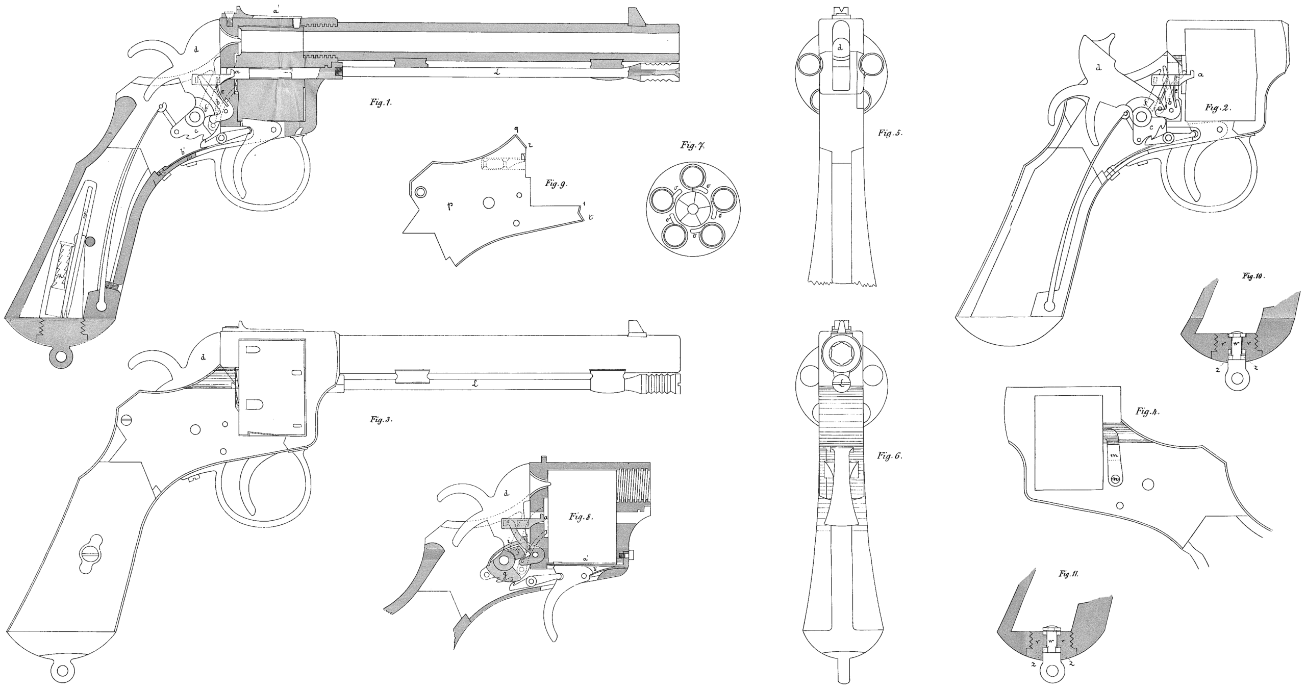
Figure 1 is a side view of a revolver according to this invention,

Figure 2 is a vertical section of the same,

Figure 3 shows the U-shaped catch,

Figure 4 is a view of the rear face of the revolver drum,

Figure 5 is an elevation of a modified form of construction, and

Figure 6 is a section of the same showing the extractor withdrawn.

Figures 7 and 8 are views of the safety lever.

The revolver drum 1 has upon its rear face a circular recess which extends to about the centre of the cartridge chambers 2 and is adapted to receive a star shaped disc 3, so arranged as to complete the drum of usual construction. This disc 3 is guided by two small rods. 4 gliding in corresponding longitudinal perforations in the drum 1 and by a central rod 5 traversing a cylindrical casing 6 fixed to the barrel 7 by screws 8 and upon which the drum 1 can freely turn.

A spring 9 bearing at one end against the rear end of the casing 6 and at its other end against a head or collar 10 on the axial rod 5 has the tendency to maintain the star shaped disc 3 in its recess in the drum. The axial rod 5 can be so acted upon as to cause the disc 3 to move out of its recess on pressure being exerted by a rod 11, which under the influence of a spring 12 bearing at one end against an abutment 13 on the barrel and at the other end against a lug or enlargement 14 on the rod 11 and tending to press the rear end of said rod against the head 10 of the rod 5.

The rod 11 carries a finger 15 which under the action of the spring 12 is pressed against a cam 16 on the butt 18, the latter & the barrel being hinged together by a pin 17. An opening or slot 19 in the casing 6 allows of a free passage of the cam 16. In a groove or recess 20 in the outer end of the rod 11 engages a small U-shaped part 21, rotatable about a pivot 22 and maintained in place by a flat spring 23 bearing against an abutment 24 which is an integral part of the U-shaped device 21. When, after firing, a quick discharge of the empty cartridges is required, the butt 18 is caused to turn about its pivot 17 in order to free the rear face of the drum 1, after which the abutment 24 is pressed to disengage the rod 11. The latter by the influence of its spring 12 moves suddenly against the head 10 of the rod 5 and the star shaped disc 3 drives the cartridge cases out of the chambers 2 of the drum.

When it is desired to carefully extract the cartridges not fired, the abutment 24 is first operated so as to disengage the rod 11 and then the butt 18 is caused to turn about the pivot 17. In this manner the rod 11 advances progressively because the head 15 is retained by the cam 16; and this motion is transmitted to the rod 5 and to the disc 3 which extracts safely the cartridges not yet utilised.

The release of the rod 11 can be automatically effected by the mere rotation of the butt 18 about its pivot 17 (Figures .5 to 8). To this end the U-shaped part 21 is replaced by a hook or lug 25 on an arm 26 of a lever pivotted at 27, this lug entering a notch 20 in the rod 11 and being maintained therein by a small spring 28 bearing against the other arm 29 of the lever. This arm 29 terminates in a finger, 30 adapted to engage with a projection 31 on the butt 18, so as to withdraw the lug 25 from the notch 20. A small lever 32, Fig. 5, mounted to turn about a fixed pivot 33 (Figs. 7 and 8) carries at its end a projection or button 34 on the underside of which is arranged a stud 35 which engages in a recess 36 of the barrel support (Fig.5). In this position on turning the butt 18 about its pivot 17 the projection 31 will strike against the stud 35 and cannot operate the lever 26, 29, so that the drum 1 can be handled without fear of a sudden ejection of the disc 3.

In order to effect a rapid extraction of the cartridges after the stud 35 of the safety lever 32 has been withdrawn from the recess 36, it is sufficient to turn the butt 18 about the pivot 17, the projection 31 of which operates the lever 26,29 and causes the disengagement of the lug 25 from the notch 20. ‘

In order to withdraw the cartridges with precaution the lever 29 is operated by hand so as to release the rod 11, after which the butt 18 is caused to turn about its pivot 17 and the rod 11 advances progressively and correspondingly operates the rod 5 and the disc 3.

Having now particularly described and ascertained the nature of my said invention, and in what manner the same is to be performed, I declare that what I claim is:—

1. A cartridge ejective device for revolvers comprising a disc such as 3 held by a spring actuated rod in a recess in the rear of the revolving cartridge drum and extending partly over the cartridge chambers a second strong rod adapted to suddenly force the disc rod outward this second rod having a forward projection bearing against a cam on a pivotted butt, and a recess adapted to engage a retaining device operated by hand or automatically and a projection on the cam arranged to cooperate with a safety device to prevent when required the operation of the releasing lever, substantially as described.

2. A cartridge ejecting device for revolvers comprising a centrally perforated revoluble cartridge drum having a centrally recessed rear face, a disc fitting in said recess so shaped as to engage behind the rear rim of the inserted cartridges, a forwardly extending central spring actuated rod connected to the disc and normally retaining it in the recess, a second spring actuated rod in front of the first rod, means for normally holding the second rod with its spring compressed and mechanism for releasing said rod to thrust out the first rod, substantially as described.

3. In mechanism of the kind described a cam such as 16, substantially as and for the purpose described.

4. In mechanism of the kind described a spring rod locking device such as 26, 29, 30 and a safety lever arm such as 32 substantially as described.

5. The complete cartridge ejecting mechanism for revolvers substantially as described or illustrated in Figs. 1 to 4 or in Figs. 5 to 8 of the accompanying drawings.

Dated this 30th day of October, 1902

BOULT, WADE & KILBURN
Agents for the Applicant.

Britain 2167

A.D. 1886, 15th February № 2167.

PROVISIONAL SPECIFICATION.

Improvements in Fire-arms with Movable Cartridge-chambers.

I, Henry Pieper, manufacturer, residing at Liege, kingdom of Belgium, do hereby declare the nature of this invention to be as follows:—

My invention relates to fire-arms having cartridge-chambers that are separate from and movable in respect to the barrel, such as revolvers and others, and its object is to prevent an escape of gas through the joint between any chamber and the barrel by means of the cartridge-case.

For this purpose the chambers are made of such length relatively to the cartridges that the case of the cartridge being in a line with the barrel, will project a short distance into the said barrel when the chamber is in contact therewith, or that the case will be caused to so project at the moment the shot is fired off, and the weapon is provided with means for producing a clearance between the cartridge case and the end of the barrel when the chamber is to be moved sideward, or to be rotated.

The said means may consist in arranging the barrel to be shifted forward and backward relatively to the cartridge-chambers, or the latter relatively to the former, by the medium of a suitable mechanical device. Or the arms are fitted, in rear of the cartridge-chambers, with a movable breech piece by which the cartridge. case may, after firing, be drawn back into the chamber by as much as is required for its clearing the barrel, or by which it may be entirely withdrawn from the chamber.

With paper cartridges loaded with shot, and in which the rim of the case is folded down inward, it is but requisite that the said rim on being expanded by the firing, overlaps the joint between the barrel and the chamber for efficiently closing the same.

Dated the thirteenth day of February 1886.

HENRY PIEPER.

By his Agent, Carl Pieper.

COMPLETE SPECIFICATION.

Improvements in Fire-arms with Movable Cartridge-chambers.

I, Henry Pieper, manufacturer, residing at Liege, Kingdom of Belgium, do hereby declare the nature of this invention and in what manner the same is to be performed, to be particularly described and ascertained in and by the following statement:—

My invention relates to fire-arms having cartridge-chambers that are separate from and movable in respect to the barrel, such as revolvers and others, and its object is to prevent, at the moment of discharge, an escape of gas through the joint between any chamber and the barrel by means of the cartridge-case.

For this purpose the chambers are made of such length relatively to the cartridges that the case of the cartridge being in a line with the barrel, will project a short distance into the said barrel when the chamber is in contact therewith, or that the case will be caused to so project at the moment the shot is fired off, and the weapon is provided with means for producing a clearance between the cartridge-case and the end of the barrel when the chamber is to be moved sideward, or to be rotated.

The said means may consist in arranging the barrel to be shifted forward and backward relatively to the cartridge chambers, or the latter relatively to the former, by the medium of a suitable mechanical device. Or the arms are fitted, in rear of the cartridge-chambers, with a movable breech-piece by which the cartridge-case may, after firing, be drawn back into the chamber by as much as is required 20 for its clearing the barrel, or by which it may be entirely withdrawn from the chamber.

On the annexed two sheets of drawings Figs. 1, 2 and 3 are sectional elevations of a gun involving my improvement, and provided with rotating cartridge-chambers, the movable parts of the gun being shown in different positions. Figs. 4 and 5 represent to a larger scale a cartridge-chamber of the said gun containing 4 ball-cartridge, and a portion of the barrel in different positions. Figs. 6 and 7 are like views of a cartride-chamber of the same or a similar gun containing a paper cartridge loaded with shot, Fig. 6 showing the cartridge before firing and Fig. 7 the empty cartridge-case after firing.

In Figs. 1, 2 and 3, b is the rear portion of the barrel, c the revolving cylinder containing the cartridge-chamber, f the hammer,d the trigger-guard pivoted at a, e the bar serving to cock the hammer and connected to the arm g of the guard d by a short link, and h a link connecting together the guard and the barrel, the latter being arranged to slide lengthwise with its rear portion in the frame i, a a are cartridges loaded with balls. The cases of these cartridges have such length that, when the barrel b is in contact with the rotating cylinder ¢, the case of the upper cartridge will project to a small extent into the barrel and thus cover or obturate the joint between the barrel and the chamber registering therewith; the said obturation being rendered complete by the expansion of the cartridge-case brought about by the discharge of the gun.

Fig. 1 shows the gun loaded and the cock set at rest. The guard d, being in normal position, keeps the barrel b against the cartridge-chamber by weans of the link h, (See also Fig. 4). When, subsequent to the discharge, the guard d has been brought into the position shown by Fig. 2, it has pushed the barrel far enough away from the cylinder c as to produce a clearance between it and the empty cartridge-case, so that the cylinder c may then commence to rotate. The guard being thereupon turned down further, the said clearance will become larger, so as to allow a loaded cartridge, with the ball projecting, to be brought in a line with the barrel by the rotation of the cylinder c, produced automatically in any known manner, This position of the parts is shown by Figs. 3 and 5. The guard at the same time causes the hammer f to be cocked through the medium of the rod e. If thereafter the guard is raised, so as to close against the stock of the gun, the barrel will be pushed upon the projecting end of the cartridge, while simultaneously the rod e is withdrawn from the hammer. The gun is then ready for firing.

With paper cartridges loaded with shot, and in which the rim of the case is folded down inward, as shown: by Fig. 6, it is not necessary that the case should project into the barrel previous to the discharge, provided the aforesaid chambers and the cartridges have such relative length that the said rim on being expanded by the discharge, overlaps the joint between the barrel and the chamber and thus closes the same, as in Fig, 7.

The described mode of obturation may be applied to any other system of repeating-arms having 4 cartridge-receiver separate from the barrel, whether the said receiver is arranged to rotate or to be moved otherwise, and it may also be used with pieces of artillery, such as mitrailleuses.

Having now particularly described and ascertained the nature and object of my said invention and in what manner the same is to be performed, I hereby declare that what I claim is:

1. In fire-arms having cartridge-chambers separate from and movable in respect to the barrel, the employment of the cartridge-case as obturator of the joint between the barre! and the chamber, in combination with means for producing a clearance between the cartridge-case and the barrel, substantially as and for the purpose described.

2. The combination, with the rotating cylinder c containing a number of cartridge-chambers, of a barrel b movable lengthwise in respect to the said cylinder, and of mechanism for thus moving the barrel, substantially as and for the purpose specified.

Dated the ninth day of November 1886.

HENRY PIEPER.

By his Agent, Carl Pieper.

France 25695

25695

BREVET D’INVENTION DE QUINZE ANS,

En date du 9 mars 1860,

Au sieur LAGRÈZE, à Paris,

Pour des perfectionnements apportés aux armes à feu dites révolvers.

Pl. XIII.

Ces perfectionnements ont rapport aux moyens d’établir à la fois, sur le même mécanisme, la faculté d’armer les révolvers indifféremment, soit par le chien comme dans les armes à feu ordinaires, soit la détente, ainsi qu’on opère plus nouvellement, en épuisant successivement et sans interruption le nombre des coups du tonnerre par la seule manœuvre de cette détente.

Ils consistent aussi dans une disposition de porte permettant, contre la partie postérieure du tonnerre, d’en dégager les ouvertures à volonté pour y introduire ou pour en retirer les cartouches.

Ils ont encore pour objet:

1º Une disposition relative à la baguette destinée à repousser les cartouches ou à décharger le révolver;

2º Diverses modifications et simplifications du mécanisme;

3º Une disposition toute nouvelle du grand ressort et son application à des fonctions multiples.

Je vais, pour faciliter l’intelligence de cet examen, en donner le détail explicatif et indiquer la marche et l’effet des pièces principales qui composent mon système.

La figure 1, pl. XIII, est la vue verticale et longitudinale d’un pistolet-révolver établi d’après ces perfectionnements; la plaque de recouvrement est supposée enlevée pour laisser à nu le mécanisme.

La figure 2 en est la vue par le bout postérieur, en section passant par la ligne 1-2, et le chien supposé retiré.

La figure 3 en est la vue extérieure par le bout opposé, du côté du canon.

Les figures 4 et 5 montrent les différentes modifications que j’apporte dans le mécanisme proprement dit et dans l’emploi et la disposition du grand ressort.

Sur le coffre ou pièce fixe principale A, qui fait corps avec le canon B et la pièce de sous-garde C, et qui se relie d’autre part à la crosse D au moyen de vis, sont fixés les centres d’oscillation respectifs a et b du chien E, dont la base forme la noix, et de la détente F qui le commande.

La partie supérieure de cette dernière est fendue longitudinalement en forme de bifurcation, pour recevoir par articulation une petite bielle e terminée en forme de crochet, à l’effet de s’agrafer dans une contrepartie formée sous la noix et d’entraîner ainsi dans son mouvement le chien E, dont le nez traverse le montant A’ qui forme la culasse, pour venir s’abattre sur la capsule disposée au fond de la cartouche.

La noix est pourvue de deux crans o dans lesquels s’engage successivement, pendant le mouvement de commande de la détente F, la gâchette ou cliquet d oscillant dans un évidement formé à cette partie de la pièce principale A, et qu’un ressort e presse constamment contre ladite noix. Lorsque les pièces E et F sont dans leur position extrême pour l’armement, l’extrémité de ce cliquet vient butter contre le fond de la bifurcation de la détente, ce qui comprime son ressort e et l’éloigne des crans d’arrêt o. Comme dans cette position extrême la bielle c se trouve également dégagée de la noix, celle-ci ou plutôt le chien E se trouve abandonné à la seule force de détente du grand ressort G, relié à ladite noix excentriquement par l’intermédiaire de la chaînette f, ce qui détermine sa chute et la percussion sur la capsule à fulminate de la cartouche qui se trouve en correspondance.

Si au lieu d’armer par la détente F, on redresse à la main et en arrière le chien E jusqu’à ce que le second des crans d’arrêt o se trouve en rapport avec la gâchette, le fond intérieur de la détente n’ira pasjusqu’à heurter la gâchette d, qui maintiendra alors le chien dans cette position jusqu’au moment où, par un mouvement du doigt sur la détente, le dégagement du cliquet aura lieu et par suite la chute du chien, comme dans le cas précédent.

Après la percussion, un ressort g’ ramène la pièce de commande c et par conséquent la détente F dans leur position primitive, c’est-à-dire à l’état de repos.

Pour commander simultanément le tonnerre H et lui imprimer chaque fois un mouvement de rotation qui lui fasse présenter exactement, en regard du canon d’une part et du chien de l’autre, une nouvelle chambre de chargement, c’est-à-dire une nouvelle cartouche, j’ai adapté à oscillation, sur le côté de la détente et excentriquement, un levier g dont la partie supérieure a pour fonction de repousser d’une dent un disque à rochet i formé par la partie centrale et postérieure saillante du tonnerre. Lorsque celui-ci a par ce mouvement amené l’une de ses ouvertures K dans la position voulue, un menton ou bossage m, formé par la partie inférieure du même levier g vient précisément s’engager dans l’un des crans d’arrêt m’ pratiqués à cet effet sur la circonférence du tonnerre, ce qui le maintient rigoureusement dans cette position jusqu’après la percussion. Ces mouvements se répètent nécessairement de la même manière pour chaque coup de feu du révolver.

La figure 2 fait voir la porte p rappelée par un ressort gå et figurée dans la position ouverte que j’établis sur l’un des côtés de la culasse ou montant fixe A’, pour dégager sur ce point les chambres Kdu tonnerre, et permettre la manœuvre du chargement et du déchargement. Cette porte est pourvue d’une saillie par laquelle on la saisit au moyen du pouce de la main droite.

La figure 3 montre la disposition de la baguette K’ mobile dans une coulisse formée par la partie supérieure d’une pièce q oscillant sur la face antérieure de la plaque principale A, et venant s’appliquer directement sur l’axe du tonnerre. En inclinant cette pièce comme l’indique le tracé, point où elle est limitée dans sa course par un goujon d’arrêt établi à sa base, cette coulisse présente la baguette K’ parfaitement au centre de l’ouverture K correspondante du tonnerre. Dans cette position, on peut faire fonctionner ladite baguette aussi profondément qu’il est nécessaire dans chacune des chambres K, et même jusqu’au delà de ces dernières, suivant le besoin de l’opération.

Dans la figure 4, nous avons modifié le mécanisme d’une manière toute particulière, en y apportant de notables simplifications. Dans une échancrure faite exprès à la partie supérieure de la détente Fse loge un levier foscillant sur l’axe b, et auquel se rattache par articulation la bielle c, articulée elle-même avec la noix ou partie inférieure du chien E, au delà de laquelle elle se prolonge pour recevoir l’extrémité du ressort G, c’est-à-dire pour remplir l’office de la chaînette employée dans le système ordinaire.

La tête de la piècefforme une saillie très-accusée, sous laquelle vient, à l’état de repos, butter la came o d’un excentrique logé dans un évidement de la détente F, et dont l’axe traverse cette dernière. Sans la présence de cette came, la détente oscillerait sous la pression du doigt sans entraîner le levier f, et par conséquent sans commander le mécanisme du chien. Mais, pendant cette pression, la buttée de la came o fait opérer au chien E un mouvement en arrière, jusqu’à ce qu’une seconde came o’, formée par le même excentrique, vienne heurter contre la base du coffre A. A ce moment, la pression de la came o’ fait basculer l’excentrique, ce qui dégage la came o de la saillie du levier f; et la bielle c étant dès lors livrée à la seule puissance du ressort G, celui-ci rabat le chien contre la culasse A’. La détente, ramenée aussitôt par l’effet du même ressort à sa position première, replace la came o sous la tête du levier f, par l’action d’un ressort s qui repousse l’excentrique, et le mécanisme est prêt à s’armer de nouveau.

Si, au lieu d’armer par la détente, on redresse le chien à la main, les mouvements précipités se répètent; mais la détente F n’oscille pas jusqu’à la rencontre de la came o’ avec la base du coffre A, ce qui permet à une troisième came o² dudit excentrique, vue en ponctué, de s’interposer sous la partie antérieure saillante d de ladite platine, pour former ainsi un point d’arrêt. Le mécanisme reste dans cette position jusqu’à ce qu’une pression exercée sur la détente F fasse basculer comme précédemment l’excentrique, d’où résulte la chute du chien et la percussion.

On remarque que par ces nouvelles dispositions la gâchette d et la chaînette f de l’exemple fig. 1 sont supprimées.

Dans la figure 5, le grand ressort G est formé d’une bande d’acier recourbée en forme d’U, et logée à l’intérieur de la sous-garde C. Ici ce ressort a deux fonctions: d’abord celle de déterminer comme à l’ordinaire la chute brusque du chien et sa percussion, ensuite celle de rappeler la détente F à sa position primitive. A cet effet, il se rattache d’une part à l’extrémité d’une pièce d terminée en forme de crochet, pour commander un levier f dont l’axe d’oscillation est porté par la base de la noix, et dont la branche inférieure vient s’engager dans une encoche formée à la partie correspondante de la détente F, afin d’en recevoir la communication de mouvement. D’autre part, le ressort G se relie à une chaînette f’, articulée excentriquement avec la détente.

En actionnant le mécanisme par cette dernière, on conçoit que les mêmes effets ne se produisent que quand la détente F est arrivée à fin de course; la branche inférieure du levierfs’échappe de l’encoche qui la retenait, ce qui laisse les pièces d et f, et par conséquent le chien E, à la seule action du ressort G.

Pour armer par le chien et arrêter le mécanisme dans cette position, on peut y adapter le système de gâchette décrit dans l’exemple représenté fig. 1, comme le montre la figure 5.

France 197423 add

2º ADDITION en date du 16 avril 1890.

(Extrait.)

Pl. VII, fig. 79 à 94.

Cette seconde addition a pour objet les perfectionnements décrits ci-après, et de bien préciser les quelques revendications principales que nous avons faites dans ledit brevet, ainsi que dans la première addition, et de les compléter au sujet de plusieurs applications spéciales que la pratique nous a fait reconnaître.

Fig. 79 à 83, cartouches-projectiles, dans lesquelles le fulminate qui compose la charge de la cartouche est renfermé dans une capsule métallique ou autre matière résistante convenable, qui fait une saillie prononcée en arrière du projectile P, dans lequel ladite capsule C est logée en partie.

Cette capsule renfermant la charge de fulminate peut remplacer la charge de l’une quelconque des cartouches-projectiles décrites dans le brevet et dans la première addition, de même que le brevet nº 175797, dans celui 164456, ainsi que dans celui 149433 et dans les additions à chacun de ces trois brevets, en sorte que les cartouches-projectiles ainsi composées peuvent être employées au lieu et place de ces mèmes cartouches.

La capsule C peut être, soit fixée et sertie d’avance dans le projectile, ou elle peut être fixée dans son logement au moment du tir, de même que pour les autres cartouches-projectiles que nous avons décrites dans le brevet et dont la charge se compose d’une capsule, fig. 1, 2, 4 et 5 du brevet, dans lesquelles la capsule est logée entièrement dans le projectile.

Pour assurer la tenue de la capsule dans la partie arrière du projectile et faciliter la pose de cette capsule au moment du tir, soit que ladite capsule soit logée entièrement dans le logement pratiqué à l’arrière du projectile, soit qu’elle soit logée partiellement dans ce logement et qu’elle fasse, par suite, saillie à l’arrière du projectile, le trou ou logement de la capsule porte des cannelures, fig. 8o, longitudinales ou obliques, qui existent sur toute la circonférence ou sur une partie seulement de la circonférence de ce trou.

Ces cannelures sont évasées ou refoulées facilement par la capsule que l’on peut introduire à la main, et elles maintiennent suffisamment cette capsule dans son logement, pour permettre de la tirer dans une de nos armes ou dans toute arme analogue.

La forme des projectiles peut être quelconque, et la butéc dans l’arme, pour assurer l’inflammation du fulminate sous le choc du percuteur, peut avoir lieu, soit par la partie avant du projectile, fig. 79, avec emploi de la capsule faisant saillie à l’arrière et sertie d’avance dans le projectile, et aussi avec emploi d’une capsule faisant saillie à l’arrière, fig. 79, oulogée entièrement dans le projectile, pour le cas de la pose de l’amorce ou capsule au moment du tir, dans un logement cannelé, décrit pour la figure 80 ou non cannelé; l’avantage de cette disposition étant principalement de posséder séparément des projectiles et des armures que le tireur réunit au moment qui lui convient le mieux, pour utiliser la cartouche ainsi composée dans un tir inoffensif ou dans un tir d’exercice, suivant la composition et la charge de la cartouche.

La butée du projectile dans l’arme peut également avoir lieu par le bourrelet B placé à la partie arrière, fig. 81, ou par la réunion de la partie avant du corps de la cartouche ou du projectile avec le bourrelet, pour former une surface tronconique à génératrice droite, fig. 82, ou courbe, fig. 83, ou par un autre endroit intermédiaire sur une longueur du corps C’ de la cartouche.

Tout ce qui précède s’applique d’ailleurs à toutes les cartouches-projectiles que nous avons décrites dans le brevet et dans la première addition, qui ne sont pas encore mentionnées dans cette seconde addition, telles que: fig. 3, 6 à 10, fig. 57 à 63 bis; et tout ce qui a été décrit et revendiqué dans ces deux documents, au sujet de ces diverses cartouches-projectiles, s’applique également au cas de l’emploi d’une capsule faisant saillie ou non à l’arrière du projectile, sertie d’avance dans cedit projectile, de même qu’au cas d’une capsule faisant ou non saillie à l’arrière du projectile, et rapportée ou placée dans son logement par le tireur, au moment du tir ou avant, si tel est son désir, conformément à ce qui a été décrit précédemment.

Les cartouches-projectiles munies d’une capsule faisant saillie à l’arrière du projectile pouvant d’ailleurs être, dans chaque cas de la pose de cette capsule, soit placées dans la chambre de l’arme avant l’introduction de l’obturateur, ou être placées à l’extrémité dudit obturateur avant sa pénétration dans l’arme.

Nous avons reconnu que les divers logements pratiqués à l’arrière des projectiles pour y loger directement le fulminate, dispositions que nous avons décrites et représentées spécialement pour les cartouches-projectiles, fig. 1, 3, 5 à 10 et fig. 57 à 63 bis, donnent d’excellents résultats, mais que pour obtenir un tir absolument précis et exempt d’inconvénients, lorsque la charge du fulminate est relativement forte, eu égard au diamètre du projectile, ce qui est le cas, par exemple, de nos cartouches-projectiles calibre 5mm 6, qui sont tirées à 30 mètres dans les armes de même calibre que celles qui tirent les cartouches actuelles à double culot métallique (bosquette ou autres similaires) il faut que le logement du fulminate ait la forme d’une cuvette plus ou moins profonde par rapport à son diamètre, c’est-à-dire que le logement doit aller en augmentant régulièrement depuis le fond jusqu’à sa partie arrière, et que la matière qui compose le projectile ne soit pas rabattue, ni ne forme bourrelet saillant sur le prolongement de la surface intérieure du logement du fulminate comprimé, la cartouche finie.

Nous obtenons également un bon tir lorsque ces dernières conditions ne sont pas exactement remplies lors de la compression du fulminate; mais ce tir est un peu moins précis que celui qui est obtenu en suivant les prescriptions indiquées ci-dessus, et que nous avons cru devoir décrire dans cette seconde addition, à l’appui des descriptions que nous avons faites dans le brevet et dans la première addition, afin de bien faire connaître que notre système de cartouche-projectile, avec logement direct du fulminate dans la partie arrière du projectile, est parfaitement praticable et donne d’excellents résultats, dans tous les cas d’emploi des diverses cartouchesprojectiles que nous avons décrites et représentées dans le brevet et dans la première addition.

Les divers obturateurs dont nous avons réclaméla propriété dans le brevet et dans la première addition pénètrent tous dans la partie arrière de la chambre de l’arme, ou dans une douille qui remplit l’office de cette chambre, pour obturer les gaz dus à l’explosion de la charge de la cartouche; or, quelles que soient les dispositions des mécanimes qui peuvent être employés pour obtenir la fermeture de la culasse, en réalisant la pénétration de l’obturateur dans la chambre, les mêmes mécanismes sont également applicables forsque l’obturateur métallique à paroi dilatable, ou autres obturateurs décrits par nous dans les documents signalés ci-dessus, est porté par le canon de l’arme sur lequel il est fixé.

Dans ce cas, la tête mobile de l’arme, ou la pièce servant à fermer la culasse, ou enfin une pièce portée par la tète mobile, enveloppe ledit obturateur, de telle sorte que, lors de l’inflammation de la charge, la pression des gaz applique la paroi de l’obturateur contre l’intérieur de la pièce qui l’enveloppe, afin d’obturer les gaz. Cette pièce-enveloppe remplit ainsi, à ce moment, le même rôle que la partie arrière du canon de l’arme, lorsque l’obturateur mobile, porté par le mécanisme de fermeture de la culasse, pénètre dans la chambre.

Tout ce qui a été dit, représenté et revendiqué dans le brevet et dans la première addition, concernant l’obturation des gaz à l’arrière d’une arme à feu, avec le cas de l’obturateur mobile pénétrant dans la chambre du canon de l’arme (ou de la douille mobile ou de la douille amovible), s’applique également dans les mêmes conditions d’emploi et de tir, au cas de l’obturateur fixé sur le canon de l’arme (ou sur la douille mobile ou sur la douille amovible), qui est alors enveloppé par une pièce de fermeture de la culasse, quelles que soient d’ailleurs la disposition et le fonctionnement du mécanisme de fermeture qui est employé.

Nous indiquons, fig. 84, à titre d’exemple, l’application d’un obturateur fixé sur le canon d’une arme à verrou, avec aiguille indépendante de la pièce-enveloppe de l’obturateur, et obturation des gaz autour de ladite aiguille percutrice, conformément à ce que nous avons déjà décrit dans le brevet et dans la première addition.

O, obturateur métallique à paroi mince extensible, fixé sur le canon C.

B, enveloppe de l’obturateur portée par la tête mobile D de l’arme.

V, verrou.

S, aiguille percutrice indépendante de l’enveloppe B, et dont le guide 1, faisant corps avec l’enveloppe B, est suffisamment long pour maintenir la cartouche M dans sa position normale.

Le verrou V, étant ramené en arrière, fait dégager l’obturateur O de son enveloppe B, ce qui permet d’introduire la cartouche M dans la chambre de l’arme, qui est alors comprise entièrement ou partiellement dans la longueur de l’obturateur O et de la partie qui sert à le fixer sur le canon C.

On voit, par ce qui précède, qu’on obtient ainsi une chambre suffisante en arrière de la cartouche, pour que les gaz puissent s’y détendre lorsqu’ils sont très brisants, ainsi que cela est le cas avec l’emploi du fulminate ou des poudres fulminantes.

Le canon de l’arme peut être considéré, soit comme fixe invariablement avec la crosse, ou comme étant mobile par rapport à la crosse considérée alors comme fixe. Chacun de ces deux cas généraux exigeant des mécanismes différents pour obtenir la fermeture hermétique de la culasse, afin de pouvoir tirer nos diverses cartouches ou toute autre cartouche combustible ou pouvant être assimilée à une cartouche combustible, nous employons les dispositions décrites plus loin, pour arriver au résultat voulu de la pénétration de l’obturateur mobile dans la chambre du canon de l’arme ou celle de l’obturateur fixé au canon, ou à la douille amovible ou à la douille mobile, dans la pièce-enveloppe portée par le mécanisme de fermeture de la culasse.

Lorsque le canon de l’arme peut être considéré comme fixé avec la crosse, la pénétration de l’obturateur porté par le mécanisme de fermeture dans la chambre de l’arme, ou la pénétration de l’obturateur porté par le canon dans la partie avant le mécanisme mobile de fermeture de la culasse, pour obtenir dans chaque cas la fermeture hermétique de ladite culasse, peut être réalisé par un procédé quelconque.

Nous indiquons, à titre d’exemples, les dispositions suivantes dont nous revendiquons particulièrement les applications, en répétition ou en plus des revendications que nous avons déjà faites dans le brevet et dans la première addition:

1º Par un mouvement en avant, suivant l’axe du canon, de tout l’ensemble du mécanisme de fermeture de la culasse, ainsi que cela existe dans les armes à verrou ou dérivant du verrou fusil Gras, par exemple.

Fig. 84, application de ce principe de fermeture de la culasse avec obturateur fixé au canon;

2º Par un mouvement de rotation plus ou moins étendu du porte-obturateur ou du porte-enveloppe, autour de son axe longitudinal, analogue à celui d’une vis, combiné avec un mouvement de rotation autour d’un axe, de l’ensemble du mécanisme de fermeture de la culasse, pour permettre de dégager suffisamment la culasse afin d’y introduire la cartouche.

L’axe de rotation de l’ensemble du mécanisme ou bloc de fermeture de la culasse pouvant d’ailleurs être placé dans une position quelconque, par rapport au plan de symétrie de l’arme passant par l’axe du canon de l’arme et par celui de la hausse, quelles que soient d’ailleurs la disposition du mécanisme de fermeture de la culasse et la position dudit axe sur l’ensemble de ce mécanisme.

Nous indiquons, fig. 85 et 86, à titre d’exemples, l’application de cette commande de l’obturateur ou de son enveloppe, suivant le cas, avec deux dispositions du mode de rotation du bloc de fermeture de la culasse.

C, canon de l’arme fixé avec la crosse.

O, obturateur mobile, pénétrant dans la chambre du canon.

B, porte-obturateur portant une vis à un ou à plusieurs filets continus, d’un pas tel que l’obturateur O rentre de la quantité voulue dans le bloc D, lorsque la poignée Ldu levier de commande de la vis du porte-obturateur B a décrit l’angle xyz, réglé dans chaque cas de la disposition d’ensemble de l’arme, pour permettre d’ouvrir la culasse afin d’introduire la cartouche dans la chambre du canon; l’angle xy z réglé à environ 135 degrés donne un bon résultat, mais on peut régler ledit angle à un autre nombre de degrés M, axe autour duquel le bloc D tourne pour ouvrir la culasse. Dans la figure 85 le bloc D se relève, tandis que dans la figure 86 ledit bloc D tourne d’un quart de tour environ, et se place en tra vers.

Après que la cartouche a été introduite dans la chambre, on remet le bloc D à la position indiquée sur le plan, après quoi, on agit sur le levier L dans la direction zyx, pour faire pénétrer l’obturateur O dans la chambre de l’arme.

La direction du mouvement du levier L varie avec la direction du pas des filets de la vis du bloc du porte-obturateur B.

P, percuteur de l’arme, dont la pointe p agit sur l’aiguille percutrice S que porte le porte-obturateur. Cette aiguille, indépendante de l’obturateur O, est ramenée en arrière au moyen d’un ressort R. L’obturateur O peut être également libre dans le porte-obturateur, mais il est alors limité dans son déplacement longitudinal qui a lieu sous le choc du percuteur.

Dans ce cas, l’aiguille percutrice est fixée dans l’obturateur O, fig. 87.

L’axe Mdu bloc D de la figure 85 peut être également placé sur le côté du canon, parallèlement ou obliquement au plan de symétrie de l’arme, ou encore être placé en avant en M’ ou en arrière en N, ou occuper une autre position quelconque convenable permettant d’ouvrir la culasse.

3º Au moyen de mouvements de translation et de rotation successifs puis combinés du porte-obturateur, ainsi que cela a lieu pour la fermeture à vis échancrée des culasses des canons de campagne ou autres de l’armée française.

Dans ce cas, l’obturateur ou l’enveloppe de l’obturateur, suivant le cas, libre ou non dans le sens de la rotation dans le bloc qui le porte, est placé dans son logement à l’arrière de l’arme, au moyen d’un mouvement rectiligne en avant, puis d’un mouvement de rotation autour de son axe, limité à une fraction de la circonférence, soit 1/6 par exemple, si les échancrures des filets de vis, qui sont généralement égales aux pleins, sont de 1/6 de la circonférence, mouvement de rotation qui produit également un mouvement combiné de translation rectiligne, par le fait de la pénétration du filet de vis du bloc de fermeture dans ceux qui sont pratiqués à l’arrière de l’arme, dans le logement dudit porte-obturateur. L’aiguille percutrice est fixée dans l’obturateur ou dans l’enveloppe dudit obturateur, forsque cet organe est libre dans le bloc qui le supporte, bien que limité dans sa course et qu’il reçoit le choc du percuteur.

Lorsque l’obturateur ou l’enveloppe est fixé avec le porteobturateur ou porte-enveloppe suivant le cas, ou qu’il est libre seulement dans le sens de la rotation autour de son axe, l’aiguille percutrice est indépendante de l’obturateur ou de l’enveloppe, et elle reçoit le choc du percuteur.

Le tout étant d’ailleurs, dans chaque cas, disposé comme nous l’avons décrit précédemment et représenté fig. 85 à 87 dans le brevet ainsi que dans la première addition. Le bloc de fermeture peut être indépendant ou relié avec un support à charnière qui permet d’ouvrir la culasse, ainsi que cela existe dans les canons français.

L’ensemble peut être également disposé comme fig. 85 et 86, dans lesquelles le bloc à vis échancrée remplace le bloc à vis à filets continus; en sorte que tout ce qui a été dit et représenté fig. 85 à 87 s’applique aussi au cas de la vis échancrée.

Dans la figure 88, l’obturateur O porté par le bloc B pénètre dans la chambre du canon de l’arme C; la tranche arrière du canon est espacée suffisamment du support R qui est fixé avec la bascule 1, le bloc porte-obturateur Best maintenu dans le support R au moyen de la vis à filets échancrés.

L’espace qui existe entre la tranche arrière du canon et la partie avant du support fixe R, doit être suffisant pour permettre d’introduire la cartouche dans l’àme du canon. Tout ce qui a été dit pour les figures 85 à 87, au sujet du mode de percussion et de l’aiguille percutrice, s’applique également au cas de la figure 88.

4º Par un mouvement de translation rectiligne du bloc qui porte l’obturateur ou l’enveloppe de l’obturateur, suivant le cas, combiné avec un mouvement de rotation de l’ensemble du mécanisme de fermeture de la culasse, autour d’un axe placé dans une position quelconque par rapport au plan de symétrie de l’arme.

Cet axe peut être placé à une distance quelconque de la tranche arrière du canon, mais il faut que la fermeture de la culasse puisse avoir lieu par le mouvement en avant de l’obturateur ou de l’enveloppe, dans la direction de l’axe du canon ou dans une direction suffisamment approchée, mouvement en avant qui peut, à la limite, se combiner et se confondre avec un mouvement circulaire seulement de l’ensemble du mécanisme.

La figure 74 de la première addition est, par exemple, de l’application de cas spécial, avec l’obturateur pénétrant dans la chambre de l’arme.

La figure 35 du brevet et la figure 75 de la première addition s’appliquent à ce quatrième cas. Il en est de même de ce qui a été dit et représenté fig. 85 à 87, en remplaçant la vis à filet continu par le bloc, fig. 35 et 75 désignées cidessus, bloc qui est commandé par un excentrique circulaire pour ouvrir ou pour fermer la culasse bloc, sur lequel peut être fixé soit l’obturateur, lorsque celui-ci pénètre dans la chambre de l’arme, soit l’enveloppe de l’obturateur lorsque ledit obturateur est fixé sur le canon, quelle que soit d’ailleurs dans chaque cas, comme pour tout ce qui précède, la disposition de l’obturateur qui est employée, et dont nous avons revendiqué la propriété au brevet et dans la première addition, de même que dans les brevets antérieurs 149433, 164456 et 175797, en combinaison avec nos cartouches-projectiles et cartouches-vitesse, ou de toute cartouche combustible ou pouvant être assimilée à une cartouche combustible.

Lorsque le canon de l’arme est mobile par rapport à la crosse de l’arme considérée comme fixe, la pénétration de l’obturateur, porté par le mécanisme de fermeture de la culasse dans la chambre de l’arme, ou la pénétration de l’obturateur porté par le canon dans la partie avant du mécanisme mobile de fermeture de la culasse, pour obtenir dans chaque cas la fermeture hermétique de la culasse, peut être réalisée par un procédé quelconque.

Nous indiquons, à titre d’exemples, les dispositions suivantes, dont nous revendiquons particulièrement les applications en répétition ou en plus des revendications que nous avons déjà faites dans le brevet et dans la première addition.

Pour ouvrir la culasse, le canon peut être animé des mouvements suivants:

1º D’un mouvement de translation suivant son axe, qui peut être réalisé au moyen de dispositions mécaniques quelconques, comme par exemple celle employée dans les pistolets du système Reinette de Paris, qui est bien connue des armuriers et des tireurs, ou en utilisant un excentrique dont l’axe se trouve dans le plan de symétrie de l’arme ou dans un plan parallèle, et qui agit dans un châssis fixé au canon ou sur deux tenons, ou une vis à filets échancrés, reliée convenablement avec le canon et agissant dans un écrou fixé avec la crosse, ou réciproquement analogue à ce que nous avons décrit précédemment, pour le troisième cas de la fermeture de la culasse avec canon fixé à la crosse; ou encore une vis à filet continu installée comme celle à filets échancrés:

2º D’un mouvement de translation suivant son axe, combiné avec un mouvement de rotation autour du même axe ou autour d’un axe parallèle, ce qui peut être réalisé au moyen d’une vis à filet continu commandée par le canon et reliée convenablement avec lui; ou encore en utilisant de même une vis à filets échancrés, analogue à ce que nous avons décrit pour le troisième cas de la fermeture de la culasse avec canon fixé à la crosse;

3º D’un mouvement de rotation autour d’un axe placé dans un plan perpendiculaire au plan de symétrie de l’arme; tel est le cas, par exemple, des fusils Lefaucheux ou autres en dérivant;

4º D’un mouvement de rotation autour d’un axe perpendiculaire à la direction de l’axe du canon, et placé dans le plan de symétrie de l’arme, autour d’un axe parallèle à la direction de ce premier axe. Plusieurs fusils ont été fabriqués suivant cette disposition;

5º D’un mouvement de rotation autour d’un axe parallèle à celui du canon, d’une amplitude suffisante pour que la chambre du canon soit découverte par le côté de la batterie, de manière à permettre d’introduire la cartouche dans ladite chambre. Plusieurs fusils ont été fabriqués suivant cette disposition. Les fusils à tonnerre multiple (genre revolver), de même que les revolvers, sont compris dans cette catégorie;

6º D’un mouvement de translation latérale, parallèlement à l’axe du canon, et quelle qu’en soit la direction par rapport au plan de symétrie de l’arme.

Nous indiquons ci-après, à titre d’exemples d’application, plusieurs dispositions qui sont respectivement applicables dans les divers cas du mouvement du canon de l’arme indiqués cidessus.

C, fig. 89 et go, canon se déplaçant longitudinalement suivant son axe pour ouvrir la culasse de la quantité voulue, permettant d’y introduire la cartouche.

O, obturateur qui pénètre dans la chambre du canon C, fig. 89, et qui pénètre dans l’enveloppe E, fig. 9o. L’obturateur 0, fig. 89, et l’enveloppe E, fig. 90, sont fixés avec le support M qui fait partie de la bascule N, ou qui est fixé avec elle.

Le percuteur Pagit sur l’aiguille S qui est libre dans l’obturateur O ou dans l’enveloppe, et les gaz sont obturés suivant l’un des procédés que nous avons décrits précédemment et dans le brevet ainsi que dans la première addition.

Le mécanisme de commande du canon, pour produire son déplacement longitudinal, peut être quelconque et, par exemple, analogue à l’un quelconque de ceux que nous avons indiqués précédemment, pour les cas des mouvements du canon nºˢ 1 et 2, auxquels les figures 89 et go sont applicables.

Dans chacun de ces cas, l’obturateur, fig. 89, ou l’enveloppe, fig. 90, peuvent être également indépendants du support M et être mobiles dans la direction de leur axe. L’aiguille percutrice peut être alors fixée dans ces parties, sur lesquelles le percuteur Pagit pour produire l’inflammation du fulminate de la cartouche, ainsi que cela est représenté fig. 91, pour le cas d’une aiguille fixée dans l’obturateur O pénétrant dans la chambre de l’arme

V, vis limitant la course de l’obturateur O.

C, fig. 92 et 93, canon de l’arme, se déplaçant pour permettre d’introduire la cartouche dans la chambre, suivant l’un quelconque des mouvements décrits précédemment de 1º à 6º.

O, obturateur pénétrant dans la chambre de l’arme, fig. 92, et pénétrant dans l’enveloppe E, fig. 93.

L’obturateur 0, fig. 92, et l’enveloppe E, fig. 93, sont fixés avec la pièce B porte-obturateur ou porte-enveloppe, qui porte une vis à filet continu et qui fonctionne pour faire pénétrer l’obturateur dans la chambre de l’arme ou dans celle de l’enveloppe, conformément à ce qui a été expliqué, fig. 85 et 86.

Pour les mouvements du canon nº 1 et 2, le canon C se déplace d’une partie de la course nécessaire, afin de permettre de charger l’arme, l’autre partie de la course étant effectuée par le porte obturateur B.

Pour les mouvements du canon nº 3 à 6, le porte-obturateur B doit effectuer la course voulue pour dégager l’obturateur de son logement, afin que le mouvement du canon puisse se produire dans chaque cas.

La disposition représentée fig. 86 peut être également employée avec chacun des mouvements nº 1 à 6, et dans les mêmes conditions générales que celles représentées fig. 92 et 93.

La vis à filet continu du porte-obturateur B, fig. 92, ou du porte-enveloppe B, fig. 93, suivant le cas, peut être remplacée pour chaque mouvement du canon ou pour une vis à filets échancrés, ainsi que nous l’avons décrit particulièrement par le mouvement nº 3 du porte-obturateur, correspondant au cas du canon fixe par rapport à la crosse, et ce, aussi bien pour les dispositions, fig. 92 et 93, que pour celle de la figure 86.

De même, le porte-obturateur B, fig. 92, ou le porte-enveloppe B, fig. 93, peut être remplacé par le bloc A et sa commande de la figure 35 du brevet, ou par celui A et sa commande de la figure 75 de la première addition, bloc qui est muni dans chaque cas de l’aiguille percutrice qui lui correspond, soit aiguille mobile pour le cas de la figure 35, et aiguille fixe dans celui de la figure 75.

Le bloc A et sa commande, fig. 35 et 75, peut être également employé avec la disposition de la figure 86, en remplacement du porte-obturateur portant une vis à filet continu.

L’excentrique E des figures 35 et 75 désignées ci-dessus, commandé par le levier L, est alors maintenu, pour les cas des figures 92 et 93, dans la pièce fixe Mreliée à la bascule de l’arme, et, pour le cas de la figure 86 dans le bloc D. La manœuvre se fait dans chaque cas, ainsi que cela a été décrit précédemment dans le brevet et dans la première addition.

Toutes les combinaisons d’aiguilles percutrices et d’obturateurs, en combinaison les unes avec les autres, qui ont été décrites précédemment dans le brevet ainsi que dans la première addition, sont applicables aux cas des figures 92, 93 et 86, avec les divers mécanismes décrits précédemment, produisant le mouvement en avant de l’obturateur ou du porteobturateur, pour le cas du canon mobile par rapport à la crosse considérée comme fixe, de même que pour les diverses dispositions décrites précédemment pour le cas du canon fixé avec la crosse.

Tout ce qui a été dit et représenté dans le brevet et dans la première addition, au sujet de l’obturation des gaz à l’arrière d’une arme à feu, tirant des cartouches-projectiles ou des cartouches-vitesse ou encore des cartouches combustibles ou pouvant être assimilées à des cartouches combustibles, s’applique et complète les diverses descriptions et dispositions générales et de détails analogues, que comprend cette seconde addition, qui forme ainsi un tout indissoluble avec notre brevet et la première addition, auxquels il faut se reporter pour tout ce qui, dans cette seconde addition, ne paraîtrait pas suffisamment explicite, aussi bien pour la description que pour le plan.

De même, les diverses dispositions et descriptions de cette seconde addition, concernant l’obturation des gaz en général, tant décrites dans ce qui précède que dans ce qui suit, s’appliquent également à ce qui a été dit et représenté dans le brevet et dans la première addition, et nous nous réservons d’ailleurs d’utiliser au besoin nos divers perfectionnements les uns avec les autres en combinaison.

Dans le brevet et dans la première addition, nous avons revendiqué l’emploi de nos divers systèmes d’obturation et de mécanismes de fermeture de culasse, pour obturer les gaz dans une arme à feu tirant une cartouche-projectile ou une cartouche-vitesse et, en général, une cartouche combustible ou pouvant être assimulée à une cartouche combustible.

Nous avons reconnu que ces divers systèmes, qui donnent d’excellents résultats dans le tir des armes à feu, peuvent être également employés pour obturer les gaz moteurs dans une arme quelconque qui utilise, pour le tir de projectiles appropriés, soit l’air comprimé ou un gaz quelconque et, en particulier, le gaz acide carbonique liquéfié.

Nous employons l’un quelconque de nos divers obturateurs, quelle qu’en soit d’ailleurs la construction, pour obturer à la partie arrière de l’arme soit l’air comprimé, soit le gaz employé comme moteur, autour du percuteur ou du distributeur, dont le déplacement sous le choc du percuteur principal laisse passer le volume nécessaire de l’un ou de l’autre de ces agents, pour projeter à une distance suffisante le ou les projectiles au dehors du canon de l’arme, quelle que soit d’ailleurs dans chaque cas la disposition du mécanisme employé pour arriver au résultat voulu.

Nous indiquons, à titre d’exemple, l’application de ce qui précède à la disposition décrite par monsieur Giffart dans le brevet nº 199087 (Emploi du gaz liquéfié pour le tir des armes).

C, fig. 94, canon de l’arme fixé avec la crosse.

R, réservoir de gaz liquéfié fixé sous le canon.

A, chien percuteur.

D, distributeur portant un obturateur métallique E actionné par le chien A articulé en U. La course du chien ou percuteur A est limitée au moyen du butoir B, que l’on règle à volonté.

S, soupape de distribution du gaz liquifié fixée au distributeur D. Cette soupape est ouverte de la quantité voulue pour laisser passer le gaz liquéfié qui se rend dans le conduit M, et, de là, dans la chambre de l’arme pour actionner le projectile P.

La soupape S se referme automatiquement après que le volume de gaz liquifié, déterminé, est sorti du réservoir R. Le distributeur D est prolongé en arrière du chien A qu’il embrasse par une partie H qui est guidée en I.

Z, ressort à boudin faisant appliquer constamment le taquet T sur le chien A, afin de maintenir la soupape S de distribution appliquée sur son siège, lorsque le chien est armé ou qu’il se trouve à sa position de repos A, à laquelle il revient automatiquement par l’effet du ressort qui l’actionne, ainsi que cela a lieu dans les platines dites rebondissantes, aussitôt qu’il a buté sur le butoir B et fait ouvrir la soupape S de la quantité voulue réglée par ledit butoir. Le ressort Z se trouvant comprimé par l’effort du retour du chien à sa position de repos A ramène alors l’obturateur E en arrière, jusqu’à ce que la soupape S soit appliquée sur son siège.

Lorsque le chien est à la position A’ de l’armé, le ressort Z est comprimé au maximum, et il applique suffisamment la soupape S sur son siège, même lorsque le réservoir Rest vide.

Le réservoir Rporte une petite soupape X qui le maintient chargé de gaz liquéfié, ce qui permet de le transporter et de le placer facilement dans son logement sous la canon de l’arme ou dans un autre emplacement convenable.

Aussitôt que le réservoir est vissé à moitié environ dans son support yla petite soupape X se trouve soulevée de sur son siège par la rencontre de sa tige t avec la soupape S, ce qui permet alors au gaz liquéfié de traverser la soupape S chaque fois que celle-ci est écartée de son siège par le choc du percuteur ou chien A.

Le ressort qui actionne le chien A, la gâchette et son ressort sont d’ailleurs installés d’une manière analogue à ce qui existe dans les carabines de tir.

Le chien A porte un bouton J, qui sert à l’amener à sa position de repos A lorsque, pour une raison quelconque, on ne veut pas tirer, le bouton J traverse le côté de la platine pour être accessible à la main du tireur.

K, bloc qui porte l’obturateur 0, lequel pénètre dans la chambre du canon C pour y obturer les gaz; l’obturateur O porte une tige b destinée à placer le projectile P à la position voulue dans la chambre du canon C’, afin que le gaz puisse agir sûrement sur lui pour le faire sortir de l’arme, le bloc K est commandé par l’excentrique circulaire Q commandé par la manivelle L, disposition que nous avons déjà brevetée, et dont il est également question dans la présente addition.

N, armature portant le bloc K; cette armature embrasse le canon C et elle est articulée en F, axe autour duquel tourne l’ensemble de l’armature N et du bloc K pour ouvrir la culasse du canon C, afin de permettre l’introduction du projectile P.

Le bloc K porte un taquet ou ergot n, suffisamment long pour entrainer l’extrémité du chien A jusqu’à la position de l’armé en A’, lorsqu’on agit sur la manivelle L pour ouvrir la culasse, en sorte que le chien A est armé en même temps qu’on ouvre la culasse du canon C.

f, frein à ressort qui agit sur l’excentrique Qpour maintenir le levier à sa position L’ par rapport à l’armature N, lorsque ladite armature est levée ou que l’obturateur O ne pénètre pas dans la chambre du canon C.

On voit, par ce qui précède, que l’ouverture du canon C se fait facilement, et que le gaz est obture hermétiquement autour du distributeur D, de même qu’à l’arrière du canon C’ par la pression que ce même gaz développe à l’intérieur de chacun des deux obturateurs E, 0, ce qui fait appliquer leurs parois sur les parties de l’arme dans lesquelles ils pénètrent. On voit également que la distribution du gaz se fait régulièrement et automatiquement par le mouvement rebondissant du chien et que, en outre, la pose du réservoir R ou son remplacement peut se refaire facilement et sûrement. Le projectile P peut être remplacé par un projectile possédant une toute autre forme et être composé de plomb massif ou non, ou être remplacé par une charge de petits plombs. De même, le canon C peut être rayé ou lisse, dans toute sa longueur ou dans une partie seulement. La charge de petits plombs peut être renfermée dans une enveloppe en papier ou autre matière suffisamment résistante.

Pour tirer avec cette arme ainsi disposée, le réservoir R étant rempli de gaz liquifié, on opère comme suit: On agit sur la manivelle Lpour ouvrir la culasse du canon en relevant l’armature N, le chien A se trouve alors à sa position de l’armé, puis on introduit le projectile-balle ou petit plomb, dans la chambre de l’arme, après quoi on abaisse l’armature N et on introdnit l’obturateur O dans la chambre, ce qui fait placer le projectile à sa position voulue, au ras du conduit M, au moyen de la tige b que porte l’obturateur O. L’arme est alors prête pour le tir, que l’on effectue en agissant sur la gachette de l’arme. Le chien agissant alors sur la soupape S, le gaz liquéfié se répand dans le conduit M, et, de là, dans la chambre de l’arme où il actionne le projectile P. On répète les mêmes opérations pour tirer un second coup, et, ainsi de suite, jusqu’à épuisement de la pression dans le réservoir R, on remplace alors ce réservoir par un nouveau, en opérant comme cela est indiqué précédemment.

Quel que soit le fluide gazeux, ou air comprimé, renfermé dans le réservoir R qui peut d’ailleurs être disposé d’une toute autre manière et posséder un volume quelconque, on voit que le fonctionnement de l’arme est assuré au moyen de deux obturateurs E, O.

On peut également remplacer le mécanisme de fermeture de la culasse de la figure 94 par un verrou analogue à ce qui existe dans le fusil Gras, pour obturer seulement la culasse et armerle chien, ou employer un autre mécanisme convenable, permettant l’emploi de l’un de nos obturateurs.

Tout ce qui se rapporte, dans le brevet, dans la première addition et dans la présente addition, à la construction et au mode de fonctionnement des divers obturateurs qui y sont mentionnés, s’applique à ce qui précède, en y supprimant ce qui concerne le fonctionnement et l’obturation des gaz autour de l’aiguille percutrice, qui n’est pas utilisée dans ce cas spécial.

Nous revendiquons, par suite, l’application de nos divers mécanismes de fermeture de culasse, ainsi que celle de nos divers obturateurs, en cas de l’emploi de l’air comprimé ou du gaz acide carbonique fiquéfié ou de tout autre gaz, pour le tir des armes, soit que ces armes tirent balle à balle ou à répétition.

Nous revendiquons également la propriété de l’ensemble de la disposition mécanique décrite ci-dessus et, en particulier, celle qui consiste à armer le percuteur au moyen du mécanisme de fermeture de la culasse, afin qu’il n’y ait qu’un seul et mème mouvement pour produire simultanément l’armement du chien du percuteur ou l’ouverture de la culasse.

Nos diverses cartouches peuvent être tirées facilement dans la même arme, fig. 94, après y avoir fait les quelques modifications suivantes: le bloc Kporte-obturateur est remplacé par un bloc portant un obturateur, dans lequel l’aiguille percutrice est fixée, conformément à ce que nous avons déjà décrit.

Ledit bloc est disposé de manière que l’obturateur puisse avancer dans la chambre de l’arme, sous le choc du percuteur A, qui agit alors sur l’ergot n convenablement disposé. L’ouverture p de communication du conduit Mavec la chambre du canon c est alors bouchée, après avoir enlevé la soupape S au moyen d’une tige que l’on visse à la place du bouchon V. L’arme est alors disposée pour le tir de nos diverses cartouches ou de toute autre cartouche combustible ou pouvant être assimilée à une cartouche combustible.

Pour tirer, il suffit d’introduire dans la chambre la cartouche qui remplace le projectile P. Nous revendiquons cette disposition en combinaison avec celle d’une arme disposée pour le tir, et qui utilise un gaz moteur quelconque: air comprimé, par exemple, un gaz liquéfié ou autre gaz convenable, ce qui fait ainsi que cette arme peut être alors considérée comme possédant un double emploi, arme utilisant les matières détonantes ou inflammables, arme utilisant un gaz moteur quelconque pour le tir des projectiles.

Load More