
British 838
Revolving Fire-arms,
LETTERS PATENT to Augusto Albini, of Genoa, and also of No. 1, New Broad Street Buildings, in the City of London, Captain in the Royal Italian Navy, for the Invention of “ Improvements in Repeating or Revolving FIRE-ARMS.,,
Sealed the 14th September 1869, and dated 19th March 1869.
PROVISIONAL SPECIFICATION left by the said Augusto Albini at the Office of the Commissioners of Patents, with his Petition, on the 19th March 1869.
I, Augusto Albini, of Genoa, and also of No. 1, New Broad Street Buildings, in the City of London, Captain in the Royal Italian Navy, do hereby declare the nature of the said Invention for “ Improvements is Repeating oe Revolving Fire-arms,” to be as follows : —
My Invention relates to revolving fire-arms in which the simultaneous extraction of all the exploded cartridge cases is effected by means of an extractor carried by a rod sliding in the axis of the cylinder containing the charge chambers, such cylinder being so jointed or hinged to the frame as to be capable of being swung or turned out of it in a vertical plane at right angles to the axis of the barrel; and my said Invention consists of the arrangements of parts herein-after described for locking the breech cylinder in the frame preparatory to firing, for unlocking the said cylinder preparatory to loading, for working and guiding the extractor, and for otherwise adding to the efficiency of revolving firearms, by which said arrangements the principle above described is rendered capable of application to existing fire-arms as well as to the construction of new fire-arms.
I moimt the charge chamber on a tubular axis fixed to an arm, wliioh when the said cylinder is in position for firing lies between the fore end of the said cylinder, and the back of the fore part of the frame, the lower end of the said arm being jointed to the lower part of the frame at the side thereof so as to admit of the said arm and eylindcr being tumel or swung out of the frame in a vertical pl°,ae at right, angles to the axis of the barrel. In the tubular axis aforesaid I fit a rod which carries the extractor and effects the locking and unlocking of the cylinder; this rod, which I will call the extractor rod, has a thumb plate or handle on its fore end, by means of which it can be slidden backwards and forwards within the said tubular axis. A liolo of a diameter corresponding to that of the fore end of the extractor rod is drilled in the fore part of the frame in a line with the axis of the cylinder and communicates with a lateral slot cut in the said frame, so as to allow the extractor rod to pass into and out of the said hole when the charge cylinder is turned on its hinge, that portion of the said rod which comes opposite the said slot when the rod is in its most forward position being cut away or reduced in diameter so as to allow7 the said rod to pass through the said slot. That portion of the said rod which is next to the thumb plate aforesaid is left cylindrical. When the charge cylinder is in position for firing and the extractor rod is pushed back the cylindrical portion aforesaid enters the hole in the fore part of the frame, and the rear end of the said rod enters a hole in the rear of the frame, thus locking the cylinder in the said frame. A spring slop is affixed to the arm which carries the cylinder, which said stop engages with notches in the extractor rod, and thus arrests the motion thereof at the required points. The extractor consists of a metal plate, the edges of which have the form of concave curves corresponding to those of the barrels. This plate when the parts are in their normal positions, lies in a recess formed in the rear end of the charge cylinder, and each of its curved edges bears against part of the flange or rim of a cartridge* A face ratchet of the ordinary kind is affixed to the hack of the extractor, by means of which ratchet the cylinder is turned. The rear end of the extractor rod passes through and slides in holes in the axis of the said extractor and ratchet, and is furnished with shoulders, one of which bears against the front of the extractor when the said rod is pushed backward, and the other against the back of the extractor when the said rod is pulled forward. The extractor is furnished with two or more guide rods, which slide in holes in the cylinder.
The action of the fire-arm is as follows :—In order to load the extractor rod is pulled forward, so as to withdraw its rear end from the hole in the rear of the frame, and to bring that part of the said rod which is of small diameter opposite to the slot in the frame. The cylinder is then turned sideways out of the frame, and the said rod is then pushed backward, carrying with it the extractor, which withdraws the cases of the exploded cartridges. The said rod is then pulled forward until the extractor is brought back to its normal position. Fresh cartridges are then inserted in the charge chambers, and the cylinder is turned into the frame and locked therein by pushing back the extractor rod.
My Invention may be modified in the following ways : —
According to one modification instead of jointing the arm carrying the tubular axis aforesaid to the side of the frame, as herein-before described, I joint the said arm to the front of the said frame, and hinge to the said arm a lever, which can be caused to act on the extractor rod for the purpose of extracting the exploded cartridge cases.
According to another modification I joint to the side of the frame twfr arms formed in one piece with the axis on which they ton. One of these arms carries the tubular axis aforesaid, and lies between the fore end of the cylinder and the back of the fore part of the frame, and the other arm lies in front of the said frame, and serves to steady the extractor rod which passes through a hole in the said arm.
According to another modification I dispense with the tubular axis herein-before described, and mount the cylinder in a ring which passes round an annular depression formed around the middle of the said cylinder which revolves in the said ring, and I joint the said ring to the side of the frame.
According to another modification I place between the rear end of the frame and the rear end of tlic cylinder a disc or shield, on the back of which is formed a circular boss, which turns in a hole in the frame. ‘Ratchet teeth arc formed on the said disc, which is connected to the cylinder by means of the extractor rod, the rear end of which is made square and engages in a square hole in the disc, so that as it is turned by means of its teeth it carries round the said cylinder.
According to another modification I joint to the lower part of the frame at the rear thereof, an arm carrying a revolving disc or shield furnished with a polygonal axis, on which the cylinder is placed, so that when all the cartridges contained in the said cylinder have been discharged it may be removed from the said axis and another loaded reserve cylinder may be placed thereon.
According to another modification in making new fire-arms I place the hinge, on which the cylinder furnished with my improved extractor rod as aforesaid turns, inside the frame instead of at the side thereof.
SPECIFICATION in pursuance of the conditions of the Letters Patent, filed by tlio said Augusto Albini in the Great Seal Patent Office on the 18th September 18G9.
TO ALL TO WHOM THESE PRESENTS SHALL COME, I, Augusto Albini, of Genoa, and also of No. 1, New Broad Street Buildings, in the City of London, Captain in the Royal Italian Navy, send greeting.
WHEREAS Her most Excellent Majesty Queen Victoria, by Her Letters Patent, bearing date the Nineteenth day of March, in the year of our Lord One thousand eight hundred and sixty-nine, in the thirty-second year of Her reign, did for Herself, Her heirs and successors, give and grant unto me, the said Augusto Albini, Her special licence that I, the said Augusto Albini, my executors, administrators, and assigns, or such others as I, the said Augusto Albini, my executors, administrators, and assigns, should at any time agree with, and no others, from time to time and at all times thereafter during the term therein expressed, should and lawfully might make, use, exercise, and vend, within the United Kingdom of Great Britain and Ireland, the Channel Islands, and Isle of Man, an Invention for “ Improvements in Repeating or Revolving Fire-arms,” upon the condition (amongst others) that I, the said Augusto Albini, my executors or administrators, by an instrument in writing under my, or their, or one of their hands and seals, should particularly describe and ascertain the nature of the said Invention, and in what manner the same was to be performed, and cause the same to be filed in the Great Seal Patent Office within six calendar months next and immediately after the date of the said Letters Patent.
NOW KNOW YE, that I, the said Augusto Albini, do hereby declare the nature of the said Invention, and in what manner the same is to be performed, to be particularly described and ascertained in and by the following statement thereof, that is to say :—
My Invention relates to revolving fire-arms in which the simultaneous extraction of all the exploded cartridge cases is effected by means of an extractor carried by a rod sliding in the axis of the cylinder containing the charge chambers, such cylinder being so jointed or hinged to the frame as to be capable of being swung or turned out of it in a vertical plane at right angles to the axis of the barrel; and my said Invention consists of the arrangements of parts herein-after described for locking the breech cylinder in the frame preparatory to firing, for unlocking the said cylinder preparatory to loading, for working the extractor, and for otherwise adding to the efficiency of revolving firearms, by which said arrangements the principle above described is rendered capable of application to existing fire-arms as well as to the construction of new fire-arms.
I mount the charge chamber on a tubular axis fixed to an arm, which when the said cylinder is in position for firing lies b-i.w-i.»r* -V.-o *muJ of the said cylinder and the back of the fore part of tue frame, the lawer end of the said arm being jointed to the lower pari of the frame at the side thereof, so as to admit of the said arm and cylinder being turned or swung out of the frame in a vertical plane at right angles to the axis of the barrel. In the tubular axis aforesaid I fit a rod which carries the extractor and effects the locking* and unlocking of the cylinder. This rod, which I will call the extractor rod, has a thumb plate or handle on its fore end, by means of which it can be slidden backwards and forwards within the said tubular axis; a hole of a diameter corresponding to that of the fore end of the extractor rod is drilled in the fore part of the frame in a line with the axis of the cylinder and communicates with a lateral slot cut in the said frame, so as 10 allow tlie extractor rod to pass into and out of the said hole when the charge cylinder is turned on its hinge, that portion of the said rod which comes opposite the said slot when the rod is in its most forward position being cut away or reduced in diameter so as to allow the said rod to pass through the said slot; that portion of the said rod which is next to the thumb plate aforesaid is left cylindrical. When the charge cylinder is in position for firing and the extractor rod is pushed back the cylindrical portion aforesaid enters the hole in the fore part of the frame, and the rear end of the said rod enters a hole in the rear of the frame, thus locking the cylinder in the said frame. A spring stop is affixed to the arm which carries the cylinder, which said stop engages with notches in the extractor rod, and thus arrests the motion thereof at the required points. The extractor consists of a metal plate, the edges of which have the form of concave curves corresponding to those of the barrels. This plate when the parts are in their normal positions, lies in a recess formed in the rear end of the charge cylinder, and each of its curved edges bears against part of the flange or rim of a cartridge. A face ratchet of the ordinary kind is affixed to the back of the extractor, by means of which ratchet the cylinder is turned. The rear end of the extractor rod passes through and slides in holes in the axis of the said extractor and ratchet, and is furnished with shoulders, one of which bears against the front of the extractor when the said rod is pushed backward, and the other against the back of the extractor when the said rod is pulled forward. The extractor is furnished with two or more guide rods which slide in holes in the cylinder.
The action of the fire-arm is as follows:—In order to load the extractor rod is pulled forward, so as to withdraw its rear end from the hole in the rear of the frame, and to bring that part of the said rod, which is of small diameter opposite to the slot in the frame. The cylinder is then turned sideways out of the frame, and the said rod is then pushed backward, carrying with it the extractor, which withdraws the cases of the exploded cartridges. The said rod is then pulled forward until the extractor is brought back to its normal position. Fresh cartridges are then inserted in the charge chambers and the cylinder is turned into the frame and locked therein by pushing back the extractor rod.
My Invention may be modified in the following ways:—
According to one modification, instead of jointing the arm carring the tubular axis aforesaid to the side of the frame, as lierein-before described, I joint the said arm to the front of the said frame and hinge to the said arm a lever, one end of which can be caused to act on the extractor rod for the purpose of extracting the exploded cartridge cases.
According to another modification I joint to the side of the frame two arms formed in one piece with the axis on which they turn. One of these arms carries the tubular axis aforesaid and lies between the fore end of the cylinder and the back of the fore part of the frame, and the other arm lies in front of the said frame and serves to steady the extractor rod which passes through a hole in the said arm.
According to another modification I dispense with the tubular axis herein-before described, and mount the cylinder in a ring which passes round an annular depression formed around the middle of the said cylinder which revolves in the said ring, and I joint the said ring to the side of the frame.
According to another modification I place between the rear end of the frame and the rear end of the cylinder a disc or shield, on the back of which is formed a circular boss which turns in a hole in the frame. Ratchet teeth are formed in the said disc, which is connected to the cylinder by means of the extractor rod, the rear end of which is made square and engages in a square hole in the disc, so that as it is turned by means of its teeth it carries round the said cylinder.
According to another modification I joint to the lower part of the frame at the rear thereof an arm carrying a revolving disc or shield furnished with a polygonal axis on which the cylinder is placed, so that when all the cartridges contained in the said cylinder have been discharged it may be removed from the said axis and another loaded reserve cylinder may be placed thereon.
According to another modification in making new fire-arms, I place the hinge on which the cylinder furnished with my improved extractor rod as aforesaid turns inside the frame instead of at the side thereof.
Having explained the nature of my Invention, I will proceed to describe with reference to the accompanying Drawings the manner in which the same is to be performed.
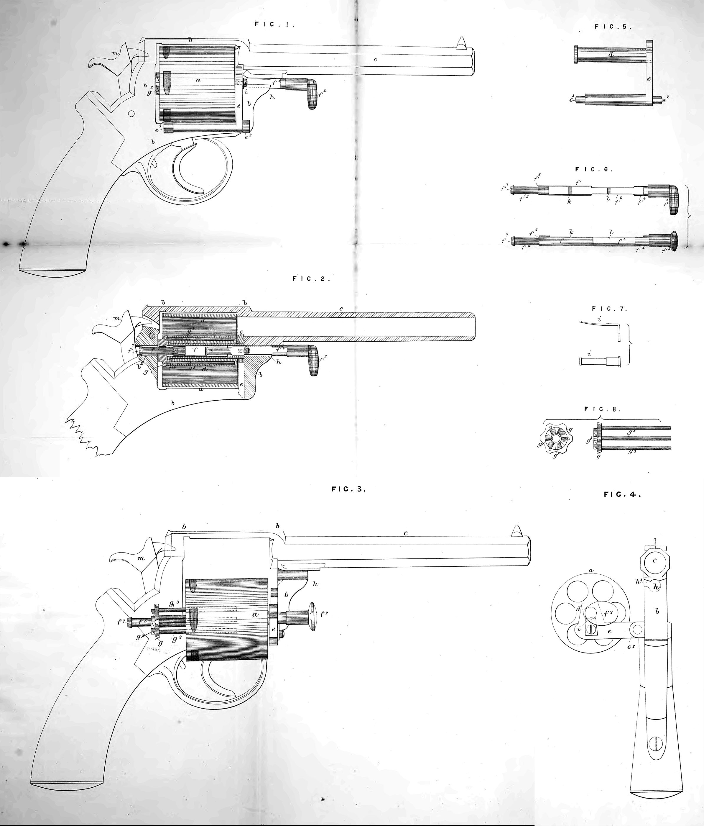
Figure 1 represents in side elevation, and Figure 2 in side elevation partly in longitudinal section a repeating or revolving pistol constructed according to my Invention; Figure 3 represents a side elevation, and Figure 4 an end elevation of the same after the revolving cylinder has been turned out of the frame and the cases of the exploded cartridges have been extracted from the chambers of the said cylinder; Figures 5, 6, 7, and 8, are parts of the same separately. The same letters of reference indicate the same parts in each Figure.
a is the revolver cylinder; b is the solid frame of the pistol, and e is the barrel, the solid frame and barrel are made in one piece as usual. Tb.e cylinder a is mounted on the tubular axis d, upon which axis the cylinder ci> is capable of revolving to bring each of its chambers in succession in a line with the barrel c. Tbe front end of the said tubular axis d is carried by the arm e, the lower horizontal part of which is jointed at e2> e8, to the side of the frame b; the axis d and arm e are sliewn separately in Figure 5. The said arm e moves in a vertical plane upon its joint, and the cylinder a is by the motion of the said arm capable of being turned out of or into the frame b as illustrated in tbe Drawing. In the tubular axis d is a rod f by which the extractor g is operated and the cylinder a locked to and released from the frame b, the rod fis shown separately in Figure 6; the said rod fis provided with a thumb plate or handle /f2 by which it may be moved backwards and forwards in the hollow axis d. In the fore part of the frame b is a channel h in which the front end of the rod f works. The hole or channel h serves as a guide to the rod f and assists in locking the cylinder a in its frame. The side A’3 of the channel h is open to permit of the removal by a lateral motion of the said rod f from the channel ht when the cylinder a is turned out of the frame b on its jointed arm e. When the rod f is pushed forward its fore end /3 enters hole b2 (see figure 2) in the back of the frame b, and securely fastens the cylinder in the frame. When the rod is in this position the rear end /* is situated in the channel h> and the said part f* prevents the rod being drawn through the lateral opening ¥ of the channel h. When it is wished to release the cylinder a the rod / is pulled towards the muzzle end of the pistol, the front end f8 of the rod is thereby withdrawn from the hole b\ and the rear part f ‘ is also removed from the channel h when the cylinder a may be turned outwards upon its jointed arm e. When in the last described position a cut away part f5 of the rod f is brought opposite the lateral opening ¥ of the channel h, and tlie said rod can pass through the said opening. The sliding motion of the rod f is limited by a spring stop i (shown separately in Figure 7) within the tubular axis d engaging with one or other of two notches or depressions k, l, in the rod/*; when the rod f is drawn forward to release the cylinder «, the stop i falls into the notch or depression k. And when the said rod is pushed outwards to operate the extractor as herein-after explained the said stop i drops into the notch or depression l, in either case the further motion of the rod is arrested. The extractor g (shown separately in Figure 8) consists of a notched disk or plate having a ratchet g2 at back, upon which ratchet the lock acts to propel forward the cylinder a. The said extractor is connected to the cylinder a, and its motion transmitted to the cylinder a by means of the guide rods g3, g3, sliding in holes in the said cylinder. The extractor g is pushed outwards from the cylinder a, when the rod f is pushed towards the back of the body by means of a shoulder fc on the said rod bearing against the inner face of the extractor, and the said extractor is pushed inwards to its place at the rear of the cylinder when the rod f is drawn towards the muzzle of the pistol by means of the head f7 on the said rod bearing against the outer face of the extractor. When the parts of the pisrol are in the respective positions represented in Figures 1 and 2 the said pistol is ready for discharge. After discharge in order to extract the cases of the exploded cartridges and reload the pistol the parts are manipulated as follows:—The hammer m is first raised to half cock, the rod / is next pulled forward by its thumb plate or handle f2, so as to withdraw the front end /s from the back of the body or frame b, and bring the cut away part fb opposite the lateral opening h2 in the frame b. By means of the said thumb plate or handle f2 the cylinder a is now turned out of the frame b upon its jointed arm e into the position represented in Figures 3 and 4, and is thereby clear of the said frame b. By next pushing outwards the rod /, the extractor g is removed from the cylinder a as illustrated in Figure 3, and the cases of the exploded cartridges are thus extracted from the chambers of the said cylinder. To reload the pistol the rod f is pulled forward and the extractor g returned to its place at the rear of the cylinder. Fresh cartridges are now introduced into the chambers of the said cylinder, the rims of the said cartridges resting against the extractor g. The cylinder is raised by the thumb plate f2 and turned on the jointed arm e into the frame b, and by pushing home the rod f the said cylinder is securely fastened in the frame and the pistol is ready for discharge.
Having now described the nature of my Invention, and the manner in which the same is to be performed, I wish it to be understood that I do not limit myself to the precise details herein described and illustrated, as the same may be varied without departing from the nature of my Invention; but I claim as my Invention of improvements in repeating or revolving fire-arms.
Firstly. Making the revolving cylinder of the said fire-arm rotate upon a tubular axis fixed to an arm jointed to the solid body or frame of the fire-arm, upon whicli jointed arm the revolving cylinder may be turned out of the said solid body or frame for extracting the cases of the exploded cartridges and for loading the revolving cylinder, substantially as herein-before described and illustrated in the accompanying Drawings.
Secondly, The arrangement or combination of parts substantially as herein-before described and illustrated in the accompanying Drawing for locking the revolving cylinder in the frame preparatory to firing and for unlocking the said cylinder for loading. Also the arrangement or combination of parts described and illustrated for working the extractor by which the simultaneous extraction of the whole of the cases of the exploded cartridges is effected.
Thirdly. The several modifications herein-before described of the said arrangements or combination of parts.
In witness whereof, I, the said Augusto Albini, have hereunto set my hand and seal, this Eighteenth day of September, in the year of our Lord One thousand eight hundred and sixty-nine.
Witness,
A. ALBINI. (l.s.)
H. n. Murdoch, 7, Staple Inn, London.