
British 161
LETTERS PATENT to Gustav Adolph Blittkowski, of the City of New York, United States of America, for the Invention of “ Improvements in Repeating Fire-arms/’
Sealed the 24th June 1856, and dated the 21st January 1856.
PROVISIONAL SPECIFICATION left by the said Gustav Adolph Blittkowski at the Office of the Commissioners of Patents, with his Petition, on the 21st January 1856.
I, Gustav Adolph Blittkowski, of the City of New York, United States of America, do hereby declare the nature of the said Invention for Improve-mjotts nr Repeating Fire-arms, to be as follows :—
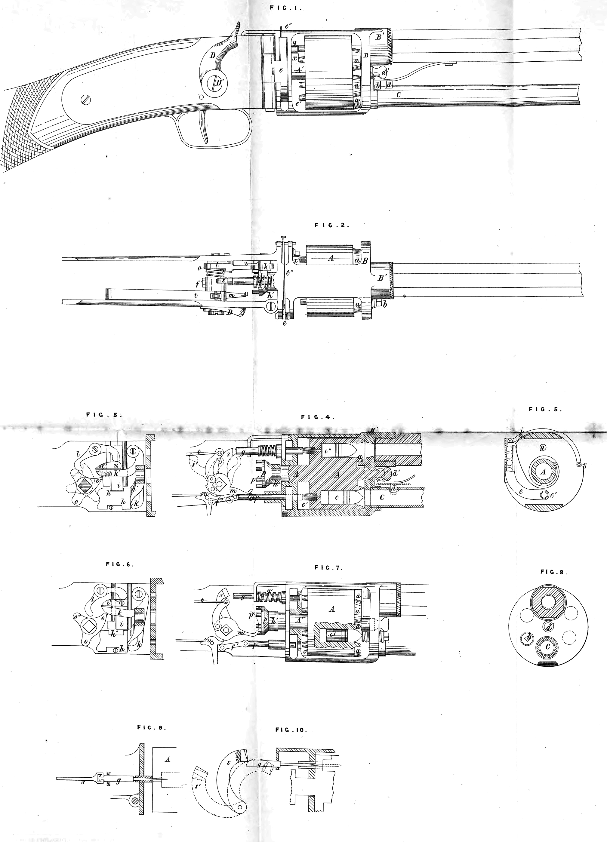
My improvement in repeating fire-arms consists mainly in the following particulars; namely, in the method of working the revolving cylinder or breech chamber, whereby the cartridge is deposited and rammed, the caps applied, and the charge conveyed to the gun barrel by the act of cocking; and in the peculiar arrangement of the lock, whereby the several reciprocating and rotating motions of the breech chamber, together with the operation of priming and firing are produced. The breech chamber has two movements, one rotating upon an axis, and the other vibratory in the direction of the said axis. The cavities in the breech chamber are bored out as usual, the nipples however being placed on the back and in a line with the bore.
On the front of the breech chamber there is likewise around each cavity a bevelled projection, which will fit within a bevelled cavity of like character at the base of the barrel. In order, therefore, to be able to turn the breech, it must first be drawn back sufficiently to allow this projection to clear. The return movement is made use of to ram home the amunition which has in the meantime been deposited from the magazine. Thus this vibratory motion of the breech enables me to effect the locking of the same to prevent rotation; it forms a very close and secure joint where it joins the barrel, and it effects the feeding and ramming of the load. At A is the breech chamber, supported upon a shaft lying parallel to the barrel and between two strong circular plates framed together. The shaft extends quite through both of these plates, being prolonged in the back part, so as to enter the lock, where vibratory and rotatory motions are given to effect the several charges for loading and firing. On the outside of the plate B, there are two nozzles, one placed directly over the other. The larger of these is at the top, as shewn at Bl, and is where the barrel is screwed on, the lower nozzle is for securing the magazine tube C. In the breech there are six charge chambers; thus, when a chamber is opposite to the barrel, there will also always be one opposite to the magazine tube, as in the sectional vie\y Fig. IV. T^he charges drop into these chambers from the magazine by gravity, the muzzle of the gun being elevated after each fire sufficiently high for the purpose, as the cartridge fits the chamber snugly by reason of a slight taper, it will require force to send it quite home. This is accomplished as followsi—In bringing the hammer of the lock to “half cock,” the breech A is drawn back, so that the bevelled mouths a, before mentioned, will stand clear of the plate B, and also clear of the bevelled concavity on the inside of the nozzle B1. The breech is thus free to revolve. Carrying the hammer on to “full cock” effects the two following motions; first, it rotates the breech one chamber onward, and when that motion is completed, the second one, viz*, in the direction of the axis, takes place, which returns the barrel back to its general place against the plate B, whereby a enters the recess in the nozzle. Through the plate B is a blunt pin 6 scpewed, so as to render it capable of adjustment. This is placed one step forward, and in such position as to point directly into one of the chambers whenever, there is one opposite to the barrel and mouth of the magazine. Thus, by pulling the hammer of the lock to “ half cock,” the breech will be drawn back from the position shewn in Fig. IV. to that shewn in Fig. VII., continuing to draw back the hammer, the breech will begin tp rotate and transfer the cartridge c, Fig. IV., to. the position c1, Figure VII., when it will stand opposite to the point of the pin b; the hammer still moving back, so soon as the rotary motion ceases, it thrusts forward the breech toward the plate B, when the pin b enters the cavity and drives home the cartridge to the position shewn at c11, Figure IV. Thus there are always four charges in the breech, viz., one just sent in from the magazine as at c, Fig. IV., one in the act of being rammed by the pin b, one in the chamber opposite the barrel as at c11, Fig. IV., and one in a chamber between the pin b and c11; as the charges fhll from the magazine by gravity into the chamber of the breech, some means must be used to prevent them moving on when the breech is withdrawn preparatory to rotating it. At d, Figures I. and IV., is a stop passing through the magazine tube, and having a spring outside tending always to withdraw it. A knob on the unattached end of this spring presses against the shaft of the breech where there is another knob d1. When the breech is locked up against the plate B, the knob on the spring presses up into the cavity behind the knob d, and thus the stop d will be partially withdrawn, and cartridges in the tube will be permitted to slide along. When the breech is drawn back, then the large part of the knob dl presses against the spring and forces the stop in, so as to punch up the cartridge and keep it back during rotation, and until an empty chamber is brought round and the breech returned to its forward position. In the partition which separates the breech from the lock is situated the cap box. This is a bent tube, shewn in the sectional view at e, Fig. V., terminating at the bottom directly opposite the nipple, which will be in place when a chamber is opposite the magaziue, and as shewn at el in the several figures, at which place there is a hole through the back of the box and likewise one through each plate of the partition for allowing the cap to be thrust through. On the inside the box has a slot, in which the end of a spring follower e11 plays to force down the caps, as shewn in Figure V. at /. Figures IV. and VII. is a rod worked from the tumbler shaft which vibrates back and forth through the inner partition plate, bottom of the cap box, and outer partitions. This pushes out the caps and deposits them in succession upon the nipples, as will be described. In exploding the cap, the hammer does not strike directly upon it, but through the medium of a strong rod placed horizontally, and situated as shewn at g. One end, it will be seen, is opposite to the nipple, upon that chamber which is then interlocked with the barrel, as in Figure IV., a spiral spring gfr always withdrawing the rod after each blow of the hammer upon it The lock will now be described. As before mentioned, all the movements of the breech necessaiy for loading and priming, are accomplished by the act of cocking; this cocking is effected by means of a lever or too attached to one end of the tumbler shaft and upon the outside of the lock plate, as represented at D, Figures I. and II., Dl being the tumbler shaft. Upon this shaft are the several devices for withdrawing, rotating, advancing, and securing the breech, driving the caps upon their nipples, and exploding the same. When the breech is in position for firing, it must be firmly locked, so as to prevent motion in either direction. The rotating is prevented by the fitting of the bevel a in the socket in the nozzle B1, and to prevent the recoil two guards are provided. To the axis A1 a slide h is attached by a curved arm h\ terminating in an eye immediately behind the toothed head for rotating. The sliding of h back and forth (therefore) produces a like movement in the breech. On the top of the slide at h11 there is a recess cut, as seen in Figures III. and VI., into which the end of a strong bar or plate i fits. This plate plays in a dovetail, fixed to the inside of one of the lock plates, and it has further a toe t1 attached, by which it is raised out of the recess A11. At k is a right angled lever or bell crank, one arm of which presses against the front end of the slide, while the other k\ extends out under the toe i1. To work this part there is on the shaft D1 a three-armed tumbler o, Figures II., III., and VI., fitted loosely by a square eye, so that it will be compelled to rotate, but may have lateral play; this is placed just upon the shaft and towards that side of the lock plate which has the slide k attached, as seen in Figure 11., and a spiral spring shown only in that Figure keeps it pressing towards that plate. In pulling the toe D, Figure I., back, the point o1 of this tumbler strikes the under side of F, Figure III., and raises it, together with the bar t, by means of its toe t1, out of the notch A11. At this moment the other arm k strikes against the end of the slide A and moves it along, this drawing back the breech by its shaft A1; and as in Figures VI. and VIL, as the lever D is continued to be pulled back, the projection o of the tumbler will approach the apposite end of the slide ifc, when the point o1 has passed over and got clear of k\ the point o will push the breech back to its first position by its action on the slide, and the locking bar i must now come back into the notch A11. This is accomplished by the point ol striking a lever /, as seen in Figure III. at the red line. The opposite end of this lever striking upon t* forces down t, and locks the slide. When this is accomplished the piece is at full cock. The slide h is then held firmly in place by the bar i as well as by the point 4?, and the bar i is prevented from rising by the position of the point o\ In the act of firing both of these are released, but another point om comes immediately under l, as shewn in Figure III., and too soon to allow of any derangement or shifting of the plate, for which indeed there is no tendency, as at this moment the gun would be raised into position for firing, and the plate would keep in place by its gravity.
As a part of the performance of the above described motions, the breech must also be rotated. On the end of the shaft A1, is a head p, having a series of teeth projecting, the said teeth being of the same number as the charge chambers. The parts for actuating this are shewn in the Figures II., IV., and VII. At m is an arm extending from the side of the regular tumbler of a lock into which the “ sear” takes. This is shaped so as to sweep past the teeth p1 in such a manner as to engage and turn the breech, but this interference will not take place until the breech, has been drawn back, as may be seen by Figures II. and IV. Thus, although m moves at the same time with the cam 0, yet the point stands so far out of the way that it does not arrive at the proper point to engage the pins until the action already described for drawing back the breech has taken place, and which will be at “ half cock m will then be in the position seen in Figure VII., ready to act upon the teeth. Here it will be seen that the curve shown by the dotted lines allows the point of m to escape from the tooth when it reaches the position p1 of Fig. VII., and this is the distance required for transferring the breech chamber from point to point in the performance already described for loading, ramming, &c.
The punch /, for applying the caps, is connected to an arm f\ affixed also to the tumbler shaft. The point of this is so far withdrawn at the commencement of the cocking that it does not arrive at the cap box until the breech has been turned by the action of m at the moment the nipple e\ Figure VII., stands close to the hole where the caps are pushed through. At this moment the punch / arrives, and thrusts out the cap by pushing agaiust its head; just then, however, the breech begins to recede, but the punch travels after it vrith greater speed, pushing the cap completely upon the nipple by the time the breech has been locked back in place, the point being, as seen in red line at e\ Fig. IV. The hammer or cock is at s, and placed upon the tumbler shaft in such position as to be in range of the end of the punch g, against which it strikes in order to explode the cap. In Figure IV. it is shewn after the blow has been given, and the position is also shewn in the red line sl when at full cock. At t is the main spring connected with the tumbler by a stirrup as usual; at u is the “ sear ” with trigger.
The operat on is as follows:—The magazine being supplied with fixed ammunition, I prepare for depositing a charge by raising the muzzle until the cartridges descend, one of which will then drop partly into a cavity of the breech as at c, Fig. IV. The toe D must then be pulled back until the gun is full cocked. This produces the set of motions already described, viz., first withdrawing the breech until the bevel a is clear of the cavity in the nozzle, pressing down the pin d to keep back the rest of the cartridges, rotating the breech one-sixth of a revolution, and thereby transferring the chamber c to the place of c\ Fig. VII., and so that it will be opposite to the rammer b, also applying the cap to the nipple of the empty chamber brought opposite the magazine, and finally the return of the breech to its first position, and the ramming of the cartridge c\ by that last-named action. As the chamber opposite to the barrel is the fourth from that opposite to the magazine, the Cock must be let down and raised that number of times in the first instance in order to work the charges round. The top charge may then be fired as usual. It has not been stated how the point o1 and the arm m avoid interference on their return with the pieces they respectively operate upon, and which are to receive action only in one direction. It was stated that the point o1 might move laterally upon the tumbler shaft, although it must rotate with it, the spiral spring, Fig. II., keeping it always directed towards the lock plate. It will be seen that the point of kl is bevilled off; therefore in firing, as the point ol strikes upon the bevil, it presses the piece along the shaft against the spring, and simply operates as a latch taking hold on the under side on the return movement. In respect to to, as the breech is at the time of its return locked forward, the pins;?1 are entirely out of reach, ns clearly seen in Fig. IV. When the trigger is drawn to fire, the hammer strikes a powerful blow upon the pin g, driving it forward upon the cap and exploding it. To strip the old shells from the nipples a small scraper x (Figures I. and II.) is-placed upon the inner partition plate, in such position as to interfere with them on the revolution of the breech, scraping off the exploded caps by the forward movement of A. The gun thus operating, may by a slight change of the construction of the end of the hammer s and of the punch g, be converted iuto a needle gun. The end of the hammer for this purpose has a dovetail, as seen in Figures IX. and X., and the end of g in contact with the hammer has a catch which takes into that dovetail, so that the punch will, by the act of cocking the gun, be withdrawn to a suitable distance when the catch rides out of the dovetail, and the hammer goes on to “full cock.” In this arrangement a needle is placed on the forward end of the punch g, and the nipples and capping apparatus are dispensed with.
SPECIFICATION in pursuance of the conditions of the Letters Patent, filed by the said Gustav Adolph Blittkowski in the Great Seal Patent Office on the Slsfc July 1856.
TO All TO WHO® THESE PRESENTS SHALL COHE, I, Gustav Ahotpk Blittkowski, of the City of New York, United States of America* send greeting.
WHEREAS Her most Excellent Majesty Queen Victoria, by Her Letters Patent bearing date the Twenty-first day of January, in the year of ou£ Lord One thousand eight hundred and fifty-six, in the nineteenth year of Her reign, did, for Herself, Her heirs and successors, give and grant unto tne, the said Gustav Adolphe Blittkowski, Her special licence that I, the said Gustav Adolph Blittkowski, my executors, administrators, and assigns, or such others as I, the said GustaV Adolph Blittkowski, my executors, administrators* find assigns, should at any time agree with, and no others, from time to tirrie and at all times thereafter during the term therein expressed, should and lawfully might make, use, exercise, and vend, within the United Kingdom of Great Britain and Ireland, the Channel Islands, and Isle of Man, an Invention for “ Improvements ifr Repeating Fire-arms,” upon the condition (amongst others) that I, the said Gustav Adolph Blittkowski, my executors or administrators, by an instrument in writing under my, or their, or one of their hands and seals, should particularly describe and ascertain the nature df the said Invention, and in what maniier the same was ‘to be performed, and eatfsd the same to be filed in the Great Seal Patent Office trithin sit calendar months next and immediately after the date of the said Letters Patent.
NOW KNOW YE, that I, the said Gustav Adolph Blittkowski, do hereby declare the nature of iny said Iuventidri, hhd in what manner the same is to be performed, to be particularly described and ascertained in aiid by thd following statement thereof, reference being had to the Drawings bertu ltd annexed, that is to say *
My improvement in repeating fire-arms consists mainly in tfie following particulars, viz.:—In the method of working the revolving cylinder dr breech chamber, whereby the Cartridge is deposited, rammed, the caps supplied, thb charge conveyed to the grin barrel by the act of cocking, add in the peculiar arrangement of the lock, thereby the several reciprocatihg And rotating motions of the breech chamber, together with the operation of priming and firing, are produced. The breech chaniber has two movements, one rotating bpon an axis, and the other vibratory in the direction of ssiid akis. The* cavities in the breech chamber are bored out as usual, the nipples, however, being placed on the back and in a line with the bore. On the front of the breech chamber there is likewise around each cavity a bevelled projection which will fit within a bevelled cavity of like character at the base of the barrel. In order, therefore, to be able to turn the breech, it must first be drawn back sufficiently to allow this projection to clear. The return movement is made use of to ram home the ammunition, which has in the mean time been deposited from the magazinethus this vibratory motion of the breech enables me to effect the locking of the same to prevent rotation, it forms a very close and secure joint where it joins the barrel, and it effects the feeding and the ramming of the load.
At A is the breech chamber, supported upon a shaft lying parallel to the barrel, and between two strong circular plates framed together. The shaft extends quite through both of these plates, being prolonged in the back part so as to enter the lock where the vibratory and rotatory motions are given to effect the several changes for loading and firing. On the outside of the plate B there are two nozzles, one placed directly over the other. The larger of these is at the top, as shown at B\ and is where the barrel is screwed on; the lower nozzle is for securing the magazine tube C. In the breech there are six charge chambers; thus, when a chamber is opposite to the barrel there will also always be one opposite to the magazine tube, as in the sectional view, Fig. IV. The charges drop into these chambers from the magazine by gravity, the muzzle of the gun being elevated after each fire sufficiently high for the purpose; as the cartridge fits the chamber snugly by reason of a slight taper, it will require some force to send it quite home. This is accomplished as follows:—In bringing the hammer of the lock to “ half-cock,” the breech A is drawn back, so that the bevelled mouths (a), before mentioned, will stand clear of the plate B, and also clear of the bevelled concavity on the inside of the nozzle B1. The breech is then free to revolve. Carrying the hammer on to “full cock’* effects the two following motions: first, it rotates the breech one chamber onward, and when that motion is completed, the second ouer viz., in the direction of the axis, takes place, which returns the breech back to its general place against the plate B, whereby (a) enters the concave in the nozzle. Through the plate B there is a blunt pin (6) screwed so as to render it capable of adjustment. This is placed one step forward, and in such position as to point directly into one of the chambers whenever there is one opposite to the barrel and mouth of the magazine. Thus, by pulling the hammer of the lock to “ half-cock,” the breech will be drawn back from the position shown in Fig. IV. to that shown in Fig. VII. Continuing to draw back the hammer, the breech will begin to rotate and transfer the cartridge (c), Fig. IV., to the position (c1), Fig. VII., when it will stand opposite to the point of the pin (b). The hammer still moving back, so soon as the rotatory motion ceases, it thrusts forward the breech towards the plate B, when the pin (b) enters the cavity and drives home the cartridge to the position shown at (cT1), Fig. IV. Thus there are always four charges in the breech, viz., one just sent in from the magazine as at (c), Fig. IV., one in the act of being rammed by the pin (6), one in the chamber opposite the barrel, as at (c11), Fig. IV., and one in a chamber between t\ie pin (6) and (c11). As the charges fall from the magazine by gravity into the chamber of the breech some means must be used to prevent them moving on when the breech is withdrawn preparatory to rotating it. At (<Z), Figs. I. and IV., is a stop passing through the magazine tube, and having a spring outside tending always to withdraw it. A knob on the unattached end of this spring presses against the shaft of the breech where there is another knob (d1). When the breech is locked up against the plate B, the knob or the spring presses up into the cavity behind the knob (d1), and thus the stop (cZ) will be partially withdrawn, and cartridges in the tube will be permitted to slide along. When the breech is drawn back, then the large part of the knob (d1) presses against the spring, and forces the stop in so as to pinch upon the cartridge and keep it back during rotation, and until an empty chamber is brought round, and the breech returned to its former position. In the partition which separates the breech from the lock is situated the cap box. This is a bent tube shown in the sectional view at (e), Fig. V., terminating at the bottom directly opposite that nipple which will be in place when a chamber is opposite the magazine, and as shown at (el) in the several Figures, at which place there is a hole through the back of the box, and likewise one through each plate of the partitions for allowing the cap to be thrust through. On the inside of the box it has a slot, in which the end of a spring follower (e11) plays to force down the caps, as shown in Fig. V. At (/), Figs. IV. and VII., is a rod worked from the tumbler shaft, which vibrates back and forth through the inner partition plate, the bottom of the cap box, and the outer partition. This pushes out the caps and deposits them in succession upon the nipples, as will be described. In exploding the cap the hammer does not strike directly upon it, but through the medium of a strong rod placed horizontally, and situated as shown at (g). One end, it will be seen, is opposite to the nipple upon that chamber, which is then interlocked with the barrel, as in Fig. IV., a spiral spring (g1) always withdrawing the rod after each blow of the hammer upon it. The lock will now be described. As before mentioned, all the movements of the breech necessary for loading and priming are Accomplished by the act of cocking. This cocking is effected by means of a lever or toe attached to one end of the tumbler shaft, «&d upon the outside of the lock plate, as represented at D, Figs. I* and II., D1 bding the tumbler shaft. Upon this shaft are the several devices for withdrawing, rotating, advancing, and securing the breech, driving the caps upon their nipples, and exploding the same. When the breech is in position for firing, it must be firmly locked, so as to prevent motion in either direction. The rotary is prevented by tbe fitting of $he bevel (o) of the socket into the nozzle Bl. Arid to prevent the roeOil, two guards are provided. To the axis A1 a slide (h) is attached by a curved arm (A1), terminating in an eye immediately back of the toothed head for rotating. The sliding of (h) therefore back and forth produces a like movement in the breech. On the top of the slide at (F1) there is a recess cut, as seen in Figs. III. and VI., into* which the end of a strong bar or plate (i) fits. This plate plays in a dovetail fixed to the inside of one of the lock plates, and it has further a toe (t1) attached, by whieh it is raised out of the recess (F1). At (k) is a right angled lever ofr bell Crank, one arm of which presses against the front end of the 6bde, while the other (F) “extends Out under the toe (t1). To work this part there is on the shaft D1 a three-arrtied tutnbler (o), Figs. II., III., atid VI., fitted loosely by a square eye, so that it will be compelled to rotate, but may have lateral plAy; this is placed first upon the shaft and toward that side of the foek plate which has the slide (h) Attached, as Seen in Fig. II* and a spiral spring, shown only in that Figure, keeps it pressing toward that plate. In pulling the toe D, Fig. I, back, the point (01) of this tumbler strikes the under side of (F), Fig. III., and raises it, together with the bat (i), by means of its toe (i1), out of the notch (A11), at this moment the other arm (k) slides against the end of the slide (h) and moves it along, febus drawing-back tbe breech by its shaft A1, and as in Figs. VI. and VII. As the lever D is continued to be pulled back, the projection (o) Of the tumbler will approach the opposite end of the slide (k). When the point (01) has passed over and got clear of (F), the point (0) Will pbsh the breech back to its first position by its action on the slide, And the locking bar (i) mhst noW cofnO back into the notch (F1). This is accomplished by the point (01) striking’ A lever (J), as seen in Fig. Ilf; at the dotted line; The opposite end of this lever striking updn (t1) forces down (t), and locks the slide. When this is accomplished the piece is at full cock. The slide (h) is then held firhdy iii place by tbe bat* (i), AS Well fis by the point (0), and the bar (t) is prevented from rising by the position of the point (01). In the act of firing, both of these ale released, but another point (0U‘) conies immediately under (?), asshewn in Fig* III* and too soon to allow of any derangement or shifting of the plate, for which indeed there is no tendency, as at this moment the gun would be raised into positidn for firing, and the plate would keep in place by its gravity* As a part of the performance of the above described motion, the breech must also be rotated* On the end of the shaft A1 is a head (p) having a series of teeth prelecting, said teeth being of the same number as the charge Chambers, The parts for actuating this are shown in the Figs. II* IV., and VIL At (tra) is bn arm extending from the side of the regular tufnbler of a lock into which the “sear*’ takes. This is shaped so as to sweep p&St the teeth (p1) in such manner as to engage and turn the breech, but this interference will not take place until the breech has been drawn back, us may be seen by Figs. IL and IV. Thus, although (m) moves at the same time with the cam (0), yet the point stands so far out of the way that it does not arrive at the proper point to engage the pins until the action already described for drawing back the breech has taken place, and which will be at “ half-cock,” (m) will then be in the position seen In Fig. VII* ready to act upon the teeth. Here it will be seen that the curve shown by the dotted lines allows the point of (m) to escape from the tooth when it reaches the position (pl) of Fig. VII., and this is the distance required for transferring the breech chamber from point to point in the performance already described for loading, ramming, ), also applying the cap to the nipple of the empty chamber brought opposite the magazine, and finally the return of the breech to its first position, and the ramming of the cartridge (c1) by that last-named action. As the chamber opposite to the barrel is the fourth from that opposite to the magazine, the cock must be let down and raised that number of times, in the first instance, in order to work the charge round. The top charge may then be fired as usual. It has not been stated how the point (o’) and the arm (m) avoid interference on their return with the pieces they respectively operate upon, and which are to receive action only in one direction. It was stated that the piece (o1) might move laterally upon the tumbler shaft, although it must rotate with it, the spiral spring, Fig. II., keeping it always directed toward the lock plate. It will be seen that the point of (F) is bevelled off; therefore, in firing, as the point (o’) strikes upon the bevel, it presses the piecn along the shaft against the spring, and simply operates as a latch, taking hold on the under side on the return movement. In respect to (m), as the breech is at the time of its return locked forward, the pins (pl) are entirely out of reach, as clearly seen in Fig. IV. When the trigger is drawn to fire, the hammer strikes a powerful blow upon the pill (g), driving it forward upon the cap, and exploding it. To strip the old shells from the nipples, a small scraper (a’), Figs. I. and II., is placed upon the inner partition plate in such position as to interfere with them on the revolution of the breech scraping off the exploded caps by its forward movements. The gun thus operating may, by a slight change of the construction of the end of the hammer (s) and of the punch (g), be converted into a needle gun. The end of the hammer for this purpose has a dovetail, as seen in Figs. IX. and X., and the end of (g), in contact with the hammer, has a catch which takes into that dovetail, so that the punch will, by the act of cocking the gun, be withdrawn to a suitable distance, at which time the catch rides out of the dovetail, and the hammer goes on to “ full cock.” In this arrangement a needle is placed on the forward end of the punch (g)9 and the nipples and capping apparatus are of course dispensed with, inasmuch as the ammunition wiil then be prepared as is usual for needle guns.
I claim, firstly, ramming the cartridge by means of the fixed rammer in combination with the reciprocating breech chamber, as described.
Secondly, the arrangement for holding and releasing the cartridges, consisting of the clamp-spring, the knob, or its equivalent, upon the axis of the breech chamber, and the magazine, as described.
Thirdly, effecting the several motions required for operating the rotating breech, by means of an axis rigidly connected therewith, and operated from one of the ends of said axis, as described.
Fourthly, the combination of the slide (h) with the axis of the revolving breech chamber, the locking bolt (i), and the tumbler (o1), or the mechanical equivalents of these several parts, for the purpose set forth.
Fifthly, in the arrangement of my said Invention as a needle gun, I claim the method of withdrawing the needle by a positive force applied thereto by means of the knob upon the end of the needle stock in combination with the claw or catch upon the end of the hammer, so arranged that becoming engaged at the moment of giving the blow, it shall cause the withdrawal of the needle in the operation of cocking the piece, as described.
In witness whereof, I, the said Gustav Adolph Blittkowski, have hereunto set my hand and seal, this Twenty-second day of May, A.D. 1856.
GUSTAV ADOLPH BLITTKOWSKI. (l.s.) Taken and declared at Her Britannick Majesty’s Consulate in the City of New York, this Twenty-third day of May 1856, before me,
(Consular) A NTH. BARCLAY,
Her Britannick Majesty’s Consul at New York.