
British 2134
Repeating Fire-arms.
LETTERS PATENT to John Talbot Pitman, of the American and European Patent Offices, No. 67, Gracechurch Street, in the City of London, for tbe Invention of “ Improvements in Repeating Fire-arms”—A communication.
Sealed the 28th November 1856, and dated the 12th September 1856.
PROVISIONAL SPECIFICATION left by the said John Talbot Pitman at the Office of the Commissioners of Patents, with his Petition, on the 12th September 1856.
I, John Talbot Pitman, of the American and European Patent Offices, No. 67, Gracechurch Street, in the City of London, do hereby declare the nature of the said Invention for “ Improvements in Repeating Fire-arms,” a communication from a foreigner residing abroad, to be as follows:—
The Invention relates to that description of repeating fire-arms, in which a chambered cylinder is arranged to rotate on an axis parallel with the barrel. The main object of the Invention is to enable the operations of rotating the breech and firing to be performed easily with a simple arrangement of mechanism operated by a single pull on one trigger. In order to accomplish this, I adopt certain arrangements and combinations of the parts of the lock, by which the hammer is made self-cocking after every fire, and the mainspring is relieved from all strain, while the hammer remains cocked. I also employ certain novel devices by which the rotating of the cylinder, the locking of the same at the time of firing, and the letting off of the hammer are effected.
The chambered cylinder has on its rear end a series of ratchet-formed notches radiating from the centre, and terminating at their outer extremities in holes drilled a little deeper than the notches. By these notches and holes operated upon by a dog working through a slot in the recoil shield, and driven by the mechanism of the lock, the cylinder is revolved and locked at the proper moments. The cylinder is provided with nipples set obliquely, as usual, and is fitted to the stock and barrel in any convenient way, so as to admit of rotation. The hammer is enclosed within the stock, where it swings on the same pivot as the trigger, which occupies the usual position. The hammer is made as long as possible consistently with its swinging inside of the stock, and is arranged direetly in line with the barrel. It has a tumbler, as usual, but the tumbler has only one notch. The sere is not attached to the trigger, but hung on a separate pin; it is in the form of a pawl, and is thrown into the notch of the tumbler by means of a spring to hold the hammer at cock.
The mainspring is of the bent form, known as the jj spring; it is fitted at its but end to work on a transverse pin or pivot, and its point is connected by a link or stirrup with the tumbler of the hammer. A small spring is so placed as to press upward against the upper limb of the mainspring, so as to give the rear portion of that spring a tendency to rise and its point to fall and draw down the tumbler, and thus throw back the hammer. This tendency can only act however while the mainspring is free to move on its pivot, which is always the case when the trigger is free; it follows that the hammer will always be thrown back and cocked after each fire.
A lever works on the same pivot with the mainspring, and has a long and short arm, so arranged that the short arm shall by pressure on the mainspring develop its elasticity at the proper moment while the long arm works the dog, which operating through a vertical slot in the recoil shield rotates the chamber cylinder and locks it when required. Motion is given to this lever by a cam, which forms part of the trigger, and operates upon a projection or toe of the lever ; this cam also throws the sere out of the notch of the tumbler to let ‘the hammer fall to discharge the piece when the trigger is pulled.
SPECIFICATION in pursuance of the conditions of the Letters Patent, filed by the said John Talbot Pitman in the Great Seal Patent Office on the 12th March 1857.
TO ALL TO WHOM THESE PRESENTS SHALL COME, I, John Talbot Pitman, of the American and .European Patent Offices, No. 67, Grace-church Street, in the City of London, send greeting.
WHEREAS Her most Excellent Majesty Queen Victoria, by Her Letters Patent, bearing date the Twelfth day of September, in the year of our Lord One thousand eight hundred and fifty-six, in the twentieth year of Her reign, did, for Herself, Her heirs and successors, give and grant unto me, the said John Talbot Pitman, Her special licence that I, the said John Talbot Pitman, my executors, administrators, and assigns, or such others as. I, the said John Talbot Pitman, or my executors, administrators, and assigns, should at any time agree with, and no others, from time to time and at all times there-. after during the term therein expressed, should and lawfully might make, use, exercise, and vend, within the United Kingdom of Great Britain and Ireland, the Channel Islands, and Isle of Man, an Invention for “Improvements in Repeating Fire-arms,” a communication from a foreigner residing abroad, upon the condition (amongst others) that I, the said John Talbot Pitman, my executors or administrators, by an instrument in writing under my, or their, or one of their hands and seals, should particularly describe and ascertain the nature of the said Invention, and in what manner the same was to be performed, and cause the same to be filed in the Great Seal Patent Office within six calendar months next and immediately after the date of the said Letters Patent.
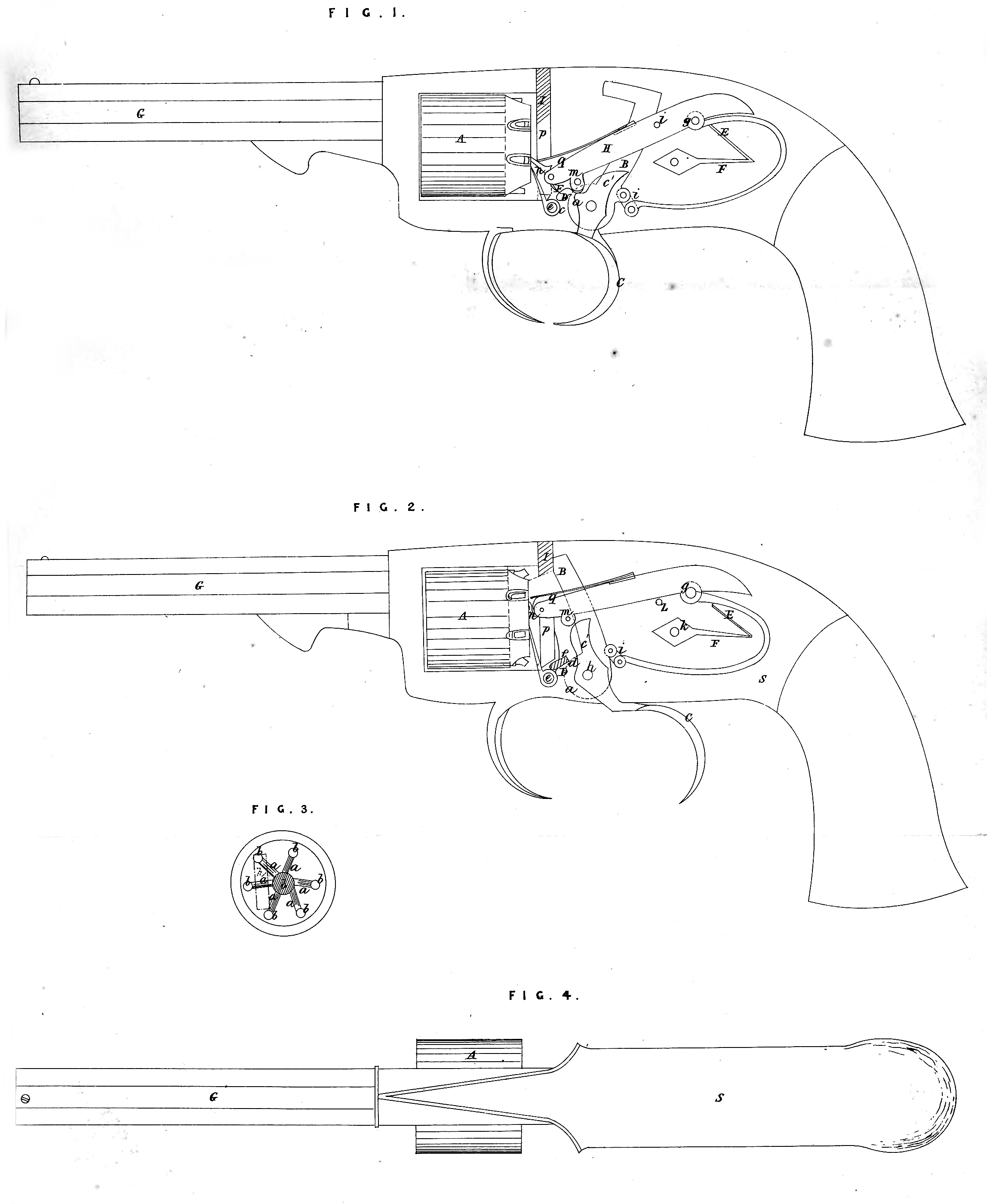
NOW KNOW YE, that I, the said John Talbot Pitman, do hereby declare the nature of my said Invention, and in what manner the same is to be performed, to be particularly described and ascertained in and by the following statement, reference being had to the accompanying Drawings, in which Figure 1 is a side view of my improved pistol, having part of one side of the stock removed to shew the lock ; this view represents all the parts in the position they assume when the pistol is not ip use. Figure 2 is a view similar to Figure 1, but shewing the. parts in the position they occupy at the instant of firing. Figure 3 is a .rear view of the cylinder, illustrating the mode of rotating and locking the cylinder. Figure 4 shews the sight at the breech. Similar letters of reference .indicate corresponding parts in the several Figures.
This Invention relates to that description of repeating fire-arms in which a chambered cylinder is arranged to rotate on an axis parallel with the barrel. The main object of the Invention is to enable the operations of rotating the breech and firing to be performed easily with a simple arrangement of mechanism operated by a single pull on one trigger. In order to accomplish the above result, an important part of the Invention consists in certain arrangements and combinations of the parts of the lock by which the hammer is made self-cocking after every fire, and the mainspring is relieved from all strain while the hammer remains cocked. Other features of the Invention consist in certain novel arrangements and combinations of mechanical devices, by which the rotating of the cylinder, the locking of the same at the time of firing, and the letting off of the hammer are effected.
In the accompanying Drawings A is the chambered cylinder, which is constructed at its rear end with a series of ratchet-formed notches a, a, radiating from the centre at equal distances apart, as shewn in Figure 3, and terminating* at their outer extremities in holes 6, b, drilled into the solid portion of the cylinder a short distance beyond the bottom of the notches. The number of the above notches and holes corresponds with the number of chambers in the cylinder. The cylinder is also intended to be provided with nipples set obliquely into the rear of the several chambers; but this arrangement of nipples is the same as that in other revolvers, and constitutes no part of my Invention. The cylinder may be fitted to the stock S and barrel G in any well-known manner, so as to be capable of the necessary rotary motions. B is the hammer, which is enclosed entirely within the stock, where it swings on the same pivot c as the trigger C, the position of which is nearly the same as in ordinary fire-arms. The hammer is made as long as possible consistently with its swinging in the stock, and is placed in the middle of the stock in line with the barrel, and so as to strike the nipple of the chamber that is uppermost. The hammer is formed with a tumbler h, substantially like the tumblers of ordinary gun locks, but; having only one notch d. D is the sere, which instead of being attached to the trigger, as in other locks, is made in the form of a pawl, and hung on a separate pin e, placed in front of the tumbler, and is thrown back into the notch d of the tumbler, as shewn in Figure 1, to hold the hammer cocked, by means of a spring f within the stock. E is tho mainspring, which is of the bent form known as the U spring. This spring, instead of having its but end secured rigidly to the stock, like the mainspring of other fire-arms, is fitted to work on a transverse pin or pivot y, and at its point it is connected by a link or stirrup i with the tumbler h. F is a smaller spring, arranged to work within the bend of the mainspring; this spring F is attached firmly to the stock at one end by a screw Jc, and the other end presses upward against the upper limb of the mainspring, producing a tendency of the rear portion of the mainspring to rise, and of the point thereof, which connects with the hammer, to fall and draw down the tumbler, and thus to throw back the hammer. Instead of the spring F, another for the same purpose may be formed, by extending in the proper direction the upper limb of the mainspring, pivotted as before named, until the end rests against a shoulder in the upper part of the stock. This tendency, however, can only act while the mainspring is free to move on the pivot g, at which time its own elasticity can have no play but by the peculiar action of mechanism yet to be described. The mainspring is always set free to move on the pivot, and therefore exerts no elasticity of its own when the trigger C is left free, and therefore the hammer is always thrown back by the action of the spring F as soon as the trigger is set free after a discharge, far enough for the sere D to fall into the notch d of the tumbler and cock it, as shewn in Figure 1* The motion beyond that point is prevented by a stop Z. H is a lever working on the same pivot g, to which the mainspring is fitted, and having a long and short arm, the latter of which is made to lap over on the mainspring E, and the former is made with a toe m to rest on a lifting cam C1, which forms one piece with the trigger. The action of the spring E on the main spring when the tiigger is set free causes the short arm of the lever H that overlaps the mainspring to be raised, and the longer arm to be consequently depressed, and the toe of the latter arm pressing on the edge of the cam C1 throws the latter back, and runs down to the bottom of it, as shewn in Figure 1, thus throwing forward the trigger; but when the trigger is pulled back the cam C1, acting on the toe wi, lifts up the long arm of the lever, as shewn in Figure 2, and causes the short arm to press down upon the mainspring and depress the bend thereof, thus producing a tendency of the point of the spring which is connected with the tumbler to rise; but as the tumbler is held by the sere, the point of the spring is prevented from rising, and thus the spring is strained so as to develope its elasticity to act in an upward direction on the tumbler. The strain of the spring increases as the drawing back of the trigger continues, but by the time the toe m is raised nearly to the top of the cam, where the lever will produce the greatest strain on the mainspring, and give it the greatest force, the cam C1 comes in contact with the sere D, and a very slight movement serves to throw the sere out of the notch d, and set free the hammer, which now having the full force of the mainspring upon it is driven violently forward to strike’ the nipple and explode the charge.
The rotation of the cylinder is effected by means of a dog n, attached by a joint to the extremity of the long arm of the lever, and passing through an upright slot p made through the recoil shield 1 on one side of the arbor t of the cylinder to the notches a, a, in the cylinder. The position of the slot p relatively to the cylinder is represented in Figure 3, where the slot is shewn in outline. The dog forms an angle with the lever, and a spring q is applied between them, which lends to throw the point of the dog towards the cylinder. When the trigger is free, as shewn in Figure 1, the dog lies in a notch occupying the position a*, as indicated in Figure 3 ; but as the dog is raised by the action of the lever II when the trigger is drawn, the rotary movement of the cylinder produced by the dog causes the hole b at the end of the notch to approach the slot, and by the time the cylinder has moved as far as required the hole is directly opposite the slot, where the dog falls into it, as shewn dn dotted outline in Figure 2, thus locking the cylinder so as to be incapable of rotating either way. The falling of the dog into the notch takes place before the sere is thrown out of the notch d. When the trigger is liberated after the discharge, and the long arm of the lever is thrown down by the action of the spring F, to effect the re-cocking of the hammer, the dog n is drawn out of the hole b, and moved down the slot p to the next notch a by the movement of the lever.
Having thus described my Invention, what I claim under the above in part recited Letters Patent, is as follows,—
1. I claim, in combination with the arrangement of the mainspring to work on a pivot, so as to be capable of relief from all strain, except at the time of firing, the application to said spring of a spring F, operating upon it, as described, to draw back and effect the cocking of the hammer, substantially as herein described.
2. I claim, in combination with the arrangement of the mainspring to work on a pivot as described, the lever H and the cam C1 on the trigger operating together, and upon the mainspring, substantially as specified, to strain and develope the elasticity of the mainspring by the act of drawing the trigger to fire.
3. I claim sere D, as arranged, entirely disconnected from the trigger, and operated upon to s$t free the tumbler by means of a cam C1 on the trigge-, substantially as herein described.
4. The attachment of the dog which operates in the ratchet a, a, on the cylinder to the, same lever H, by which the strain is thrown on to the mainspring.
5. And, finalLy, I claim, the arrangement of the slot p in the recoiled shield, and the holes 5, b, at the end of the ratches a, a, on the cylinder, whereby the cylinder is locked, so as to be incapable of rotation in either direction before the hammer is let off, substantially as herein set forth and described.
In witness whereof, I, the said John Talbot Pitman, have hereunto set my hand and seal, this Twelfth day of March,’ in the year of our Lord One thousand eight hundred and fifty-seven.
JOHN TALBOT PITMAN. (l.s.)