
British 1081
LETTERS PATENT to Francois Alexandre Le Mat, of New Orleans, in tbe United States of America, Colonel Aide-de-Camp, and Charles Frederic Girard, of Washington, in the United States of America, Doctor of Medicine, for the Invention of “ Improvements in the Construction op Revolving and Repeating Fire-arms, Part of which Invention is also
APPLICABLE TO OTHER ARMS.”
Sealed the 10th October 1862, and dated the 16th April 1862.
PROVISIONAL SPECIFICATION left by the said Fran$ois Alexandre Le Mat and Charles Frederic Girard at the Office of the Commissioners of Patents, with their Petition, on the 15th April 1862.
We, Francois Alexander Le Mat, of New Orleans, in the United States of America, Colonel Aide-de-Camp, and Charles Frederic Girard, of Washington, in the United States of America, Doctor of Medicine, do hereby declare the nature of the said Invention for “ Improvements in the Construction o; Revolving and Repeating Fire-arms, Part op which Invention 19
ALSO APPLICABLE TO OTHER ARMS,” to be as follows I—
Our Invention, as far as it applies to revolving and repeating fire-arms, consists in an improved lock, and in an improved means of fixing and of rotating the revolving chamber when required for the purpose of firing the charge from one of the compartments, and of locking the chamber when the arm is being carried, and of causing the chamber to rotate after the discharge of one of the compartments to present another compartment for being discharged.
The part of the Invention which applies to other fire-arms as well as to revolving arms is the lock. The lock is constructed as follows :—The body of the hammer is centred upon a pin held in the stock ; it has a circular aperture made at the back and just above the heel, and to this heel a link is pinned which receives the fore end of the mainspring, which is a simple straight blade of steel, the rear end of which is held in a jaw or otherwise attached to the under part and inside of the stock. The breast of the hammer is formed with two notches for the cock and half cock; a trigger and trigger spring complete the lock for ordinary fire-arms. For arms with revolving breech chambers the following parts are added:—On the near side of the body of the hammer and at the lower part thereof a link is screwed; this link is formed with two projecting studs, one on the rear, which enters an aperture made for its reception in the body of the hammer, and the other, projecting from the opposite side and fore end, enters an eye in the lower end of a paul, the upper end of which takes into the ratchet on the rear of the revolving chamber. At the proper time this ratchet comes into action and drives round the chamber. In the far side of the stock a recess is formed for the reception of a circular spring, let into and secured to the far side of the body of the hammer; this spring is made with a projecting lip, which takes into a notch made in the barrel of a bolt, the fore end of which is thinned off, passes through the shield at the rear of the chamber, and enters one or other of a series of holes made in the rear thereof; a spiral spring is fitted in the recess in the stock, and keeps the locking bolt engaged in one or other of the said holes until forced back by the spring on the body of the hammer engaging in the notch, and when so forced back the chamber is ready for being revolved by the ratchet as before described.
SPECIFICATION in pursuance of the conditions of the Letters Patent, filed by the said Francis Alexandre Le Mat and Charles Frederic Girard in the Great Seal Patent Office on the 15th October 1862.
TO ALL TO WHOM THESE PRESENTS SHALL COME, we, Francois Alexandre Le Mat, of New Orleans, in the United States of America, Colonel Aide-de-Camp, and Charles Frederic Girard, of Washington, in the United States of America, Doctor of Medicine, send greeting.
WHEREAS Her most Excellent Majesty Queen Victoria, by Her Letters Patent, bearing date the Fifteenth day of April, in the year of our Lord One thousand eight hundred and sixty-two, in the twenty-fifth year of Her reign, did, for Herself, Her heirs and successors, give and grant unto us, the said Francois Alexandre Le Mat and Charles Frederic Girard, Her special licence that we, the said Franjois Alexandre Le Mat and Charles Frederic Girard, our executors, administrators, and assigns, or such others as we, the said Francois Alexandre Le Mat and Charles Frederic Girard, our executors, administrators, and assigns, should at any time agree with, and no others, from time to time and at all times thereafter during the term therein expressed, should and lawfully might make, use, exercise, and vend, within the United Kingdom of Great Britain and Ireland, the Channel Islands, and Isle of Man, an Invention for “ Improvements in the Construction op Revolving and Repeating Fire-arms, Part op which Invention is also applicable to other Arms,” upon the condition (amongst others) that we, the said Francis Alexandre Le Mat and Charles Frederic Girard, or one of us, our executors or administrators, by an instrument in writing under our, or their, or one of our or their hands and seals, should particularly describe and ascertain the nature of the said Invention, and in what manner the same was to be performed, and cause the same to be filed in the Great Seal Patent Office within six calendar months next and immediately after the date of the said Letters Patent.
NOW KNOW YE, that we, the said Francis Alexandre Le Mat and Charles Frederic Girard, do hereby declare the nature of our said Invention, and in what manner the same is to be performed, to be particularly described and ascertained in and by the following statement thereof, reference being had to the Drawings hereunto annexed, that is to say:—
Our Invention, as far as it applies to revolving and repeating fire-arms, consists in an improved lock, and in an improved means of fixing, and of rotating the revolving chamber when required for the purpose of firing the charge from one of the comparments, and of locking the chamber when the arm is being carried, and of causing the chamber to rotate after the discharge of one of the compartments to present another compartment for being discharged. The part of the Invention which applies to other fire-arms as well as to revolving arms is the lock.
The lock is constructed as follows:—The body of the hammer is centred upon a pin held in the stock, it has a circular aperture made at the back and just above the heel, and to this heel a link is pinned which receiyes the fore end of the main spring, which is a simple straight blade of steel, the rear end of which is held in a jaw, or otherwise attached to the under part and inside of the stock. The breast of the hammer is formed with two notches for the cock and half cock ; a trigger and trigger spring complete the lock for ordinary fire-arms. For arms with revolving breech chambers the following parts are added:—On the near side of the body of the hammer and at the lower part thereof a link is screwed ; this link is formed with two projecting studs, one on the rear which enters an aperture made for its reception in the body of the hammer, and the other, projecting from the opposite side and fore end,, enters an eye in the lower end of a paul, the upper end of which, takes into the ratchet on the rear of the revolving chamber. At the proper time this ratchet comes into action and drives round the chamber. In the far side of the stock a recess is formed for the reception of a circular spring, let into and secured to the far side of the body of the hammer; this spring is made with a projecting lip, which takes into a notch made in the barrel of a bolt, the fore end of which is thinned off, passes through the shield at the rear of the chamber, and enters one or other of a series of holes made in the rear thereof; a spiral spring is fitted in the recess in the stock, and keeps the locking bolt engaged in one or other of the said holes, until forced back by the spring on the body of the hammer engaging in the notch, and when so forced back, the chamber is ready for being revolved by the ratchet as before described.
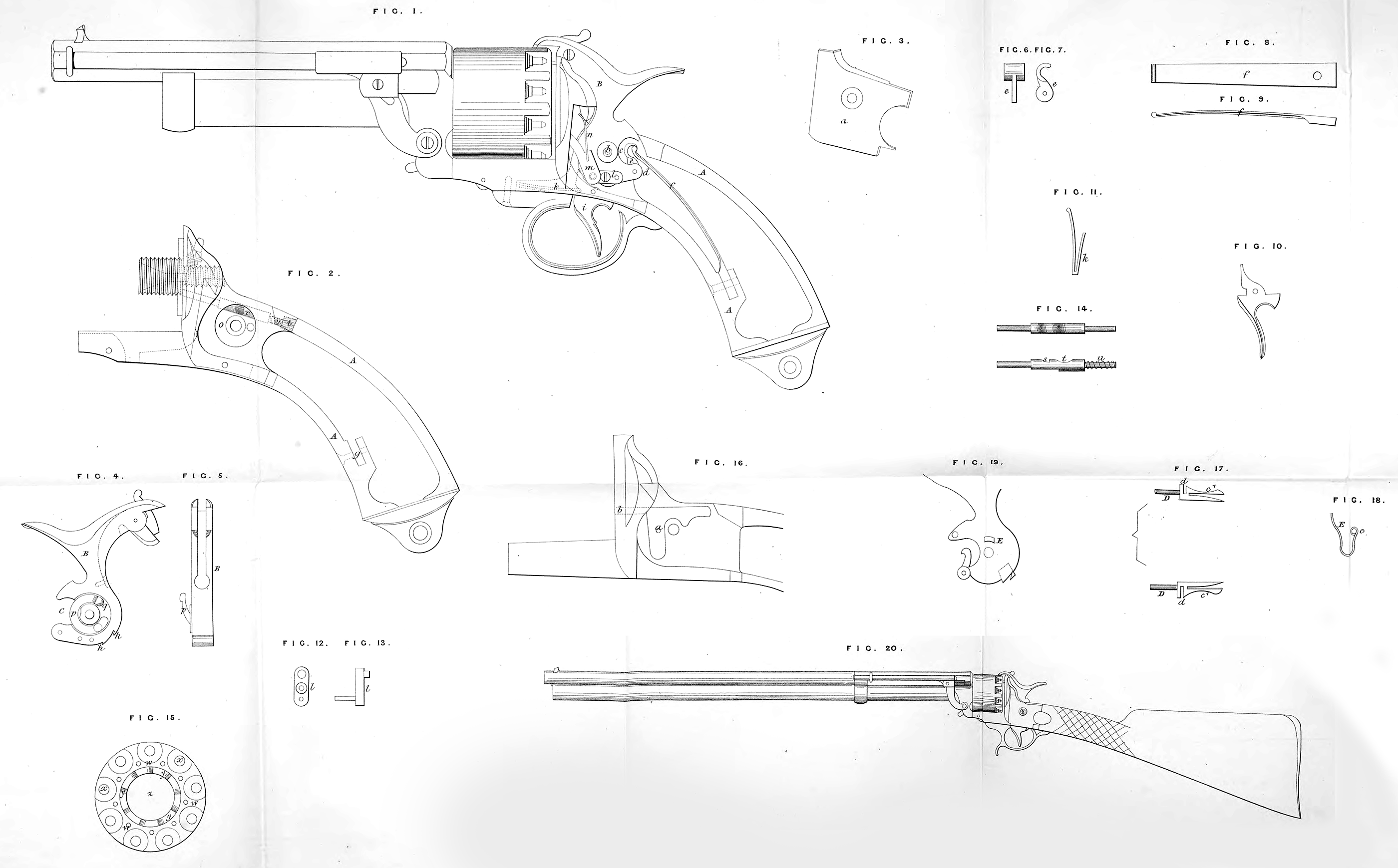
In the accompanying Drawings we have shewn our Invention applied to one of our patent pistols having a central barrel, round which a breech chamber with nine charge compartments is free to revolve, there is the usual barrel common to all the compartments. Figure I, is a longitudinal section of such a pistol with our present Invention applied thereto. •
A, is a malleable cast-iron stock, shewn detached at Figure 2, the side plate a, Figure 3, and the wood of the stock are removed for clearness; B, is the hammer, shewn detached in side elevation at Figure 4, and in front view at Figure 5; b, is the pin on which the hammer is centred; c, is the aperture made at the back and just above the heel d; eis the link shewn in front elevation at Figure 6, and in side view at Figure 7, which is pinned to the heel dj and holds the fore end of the main spring/, which is a straight blade of steel as shewn in plan at Figure 8, and in side elevation at Figure 9. The back end of this spring is secured by a pin in a recess g in the interior of the stock; the notches on the breast of the hammer for the cock and half cock are shewn at h, Figure 4; i is the trigger, shewn detached in side elevation at Figure 10, and k Figure 11, is the trigger spring. As before stated, we make the following additions for arms with revolving chambers:—l is a link, shewn detached in front and side elevations at Figures 12 and 13. It is formed with two projecting pins as shewn at Figure 13; one of these pins enters a hole made to receive it in the thickness of the hammer, while the other enters an eye in the lower end of the paul or lever m; the loop is further secured to the hammer by a screw pin; n is a spring for keeping the upper end of the paul in the ratchet on the rear of the revolving chamber; o, Figure 2, is a recess made in the inside of the lock plate on the far side of the stock, in which the circular spring p, screwed to the far side of the hammer, see Figure 4, works; q is a projecting lip in which one end of spring p terminates ; r is the locking bolt shewn in position in the stock at Figure 2, and detached at Figure 14; s, the notch against which the lip on the spring p bears; the curve t assists the entrance of the lip into the notch ; u is the coiled spring, and v is a nut for keeping the bolt in position. Figure 15 is an elevation of the back end of the revolving chamber; w, w, are the holes into one of which the fore end of the locking bolt enters; x, x, are the nipples, y, y the ratchet teeth, and z is the aperture through which the central barrel passes.
Figures 16, 17, 18, and 19, represent a modification of the locking apparatus. Figure 16 shews so much of the interior of the far-side lock plate as is necessary to explain this modification. Instead of the circular recess, we make a recess of the form shewn at Figure 16, and we fix therein the pin a; we make the locking bolt D of the form shewn at Figure 17, and place it in the recess with the front end in the groove h; we fit the eye c, in which one end of the spring E, Figure 18, terminates on the pin a, and engage the other end in the chamber d\ d\ in the bolt. F is a projection on the side of the hammer which coming against the spring catch cl on the rear of the bolt, withdraws it from one of the holes w, w in the rear of the chamber, and allows of the chamber being moved one division by the paul when the spring catch is released, and the bolt is pressed forward by the spring E into another hole in the chamber, whereby it is locked until the compartment presented for firing has been discharged. Figure 20 is an elevation of a carbine with our improvements applied.
And having now described the nature of our said Invention, and in what manner the same is to be performed, we declare that we claim,—
First, the improved lock herein-before described and represented in the accompanying Drawings for revolving and other fire arms.
Second, the arrangements of parts for rotating and locking the chambers of revolving fire-arms herein-before described and represented in the accompanying Drawings.
In witness whereof, I, the said Charles Frederic Girard, have hereunto set my hand and seal, this Ninth day of October, One thousand eight hundred and sixty-two.
CHARLES FREDERIC GIRARD. (l.s.)
Witnesses,
E. Gautherin,
A. Binet (1, Rue Laffitte).