
British 1592
LETTERS PATENT to William Palmer* of the City and State of New York, United States of America, for the Invention of “Improvements in Revolving Fire-arms.”
Sealed the 25th July 1862, and dated the 27th May 1862,
PROVISIONAL SPECIFICATION left by the said William Palmer at the Office of the Commissioners of Patents, with his Petition, on the 27th May 1862.
I, William Palmer, of the City and State of New York, United States of America, do hereby declare the nature of the said Invention for “ Improvements in Revolving Fire-arms,” to be as follows: —
I make use of a barrel, either rifled or plain, and of a size adapted to the ball required. This barrel is open at the rear end, and is set in a stock suitably constructed, and the whole arm may be adapted to hand use on a rest, or be mounted on a carriage and adjusted on a suitable swivel by convenient mechanism. My cartridges or charges are supplied by short sections of a barrel, or chambers, as I term them, which are loaded with powder and ball, and provided with a detonating cap or powder to be exploded by a hammer. I provide a number of these chambers, which, after being properly loaded, are placed in a slide or hopper that conveys them to a rotary carrier moved by automatic mechanism that takes the said chambers successively, and conveys one at a time to the line of the barrel at the rear thereof, and pauses while the chamber is pressed up tightly against the barrel and fired ; then the carrier and empty chamber are drawn back, the carrier partially revolves, bringing another loaded chamber to the rear of the barrel, and conveying the discharged chamber to a point where it drops away to be reloaded. The carrier is revolved, held pressed towards the barrel, and withdrawn by the action of a cam revolved by a crank, and said cam is made with a diagonal groove across its periphery that acts successively on pins at the rear of the rotary carrier to turn the same, and with a greater radius on one side than the other to press the chambers up to the barrel. The hammer is held back by a cam on the shaft of aforesaid cam, except when projected forward by a spring to fire the piece when the chamber is pressed to the barrel.
SPECIFICATION in pursuance of the conditions of the Letters Patent, filed by the said William Palmer in the Great Seal Patent Office on the 25th November 1862.
TO ALL TO WHOM THESE PRESENTS SHALL COME, I, William Palmeb, of the City and State of New York, United States of America, send greeting.
WHEREAS Her most Excellent Majesty Queen Victoria, by Her Letters Patent, bearing date the Twenty-seventh day of May, in the year of our Lord One thousand eight hundred and sixty-two, in the twenty-fifth year of Her reign, did, for Herself, Her heirs and successors, give and grant unto me, the said William Palmer, Her special license that I, the said William Palmer, my executors, administrators, and assigns, or such others as I, the said William Palmer, my executors, administrators, and assigns, should at any time agree with, and no others, from time to time and at all times thereafter during the term therein expressed, should and lawfully miglit make, use, exercise, and vend, within the United Kingdom of Great Britain and Ireland, the Channel Islands, and Isle of Man, an Invention for “ In— pbovements in Revolvino Fibe-abhs,’* upon the condition (amongst others) that I, the said William Palmer, by an instrument in writing under my hand and seal, should particularly describe and ascertain the nature of the said Invention, and in what manner the same was to be performed, and cause the same to be filed in the Great Seal Patent Office within six calendar months next and immediately after the date of the said Letters Patent.
NOW KNOW YE, that I, the said William Palmer, do hereby declare the nature of my said Invention, and in what manner the same is to be performed, to be particularly described and ascertained in and by the following statement, reference being had to the Drawing hereunto annexed, and to the letters and figures marked thereon (that is to say):—
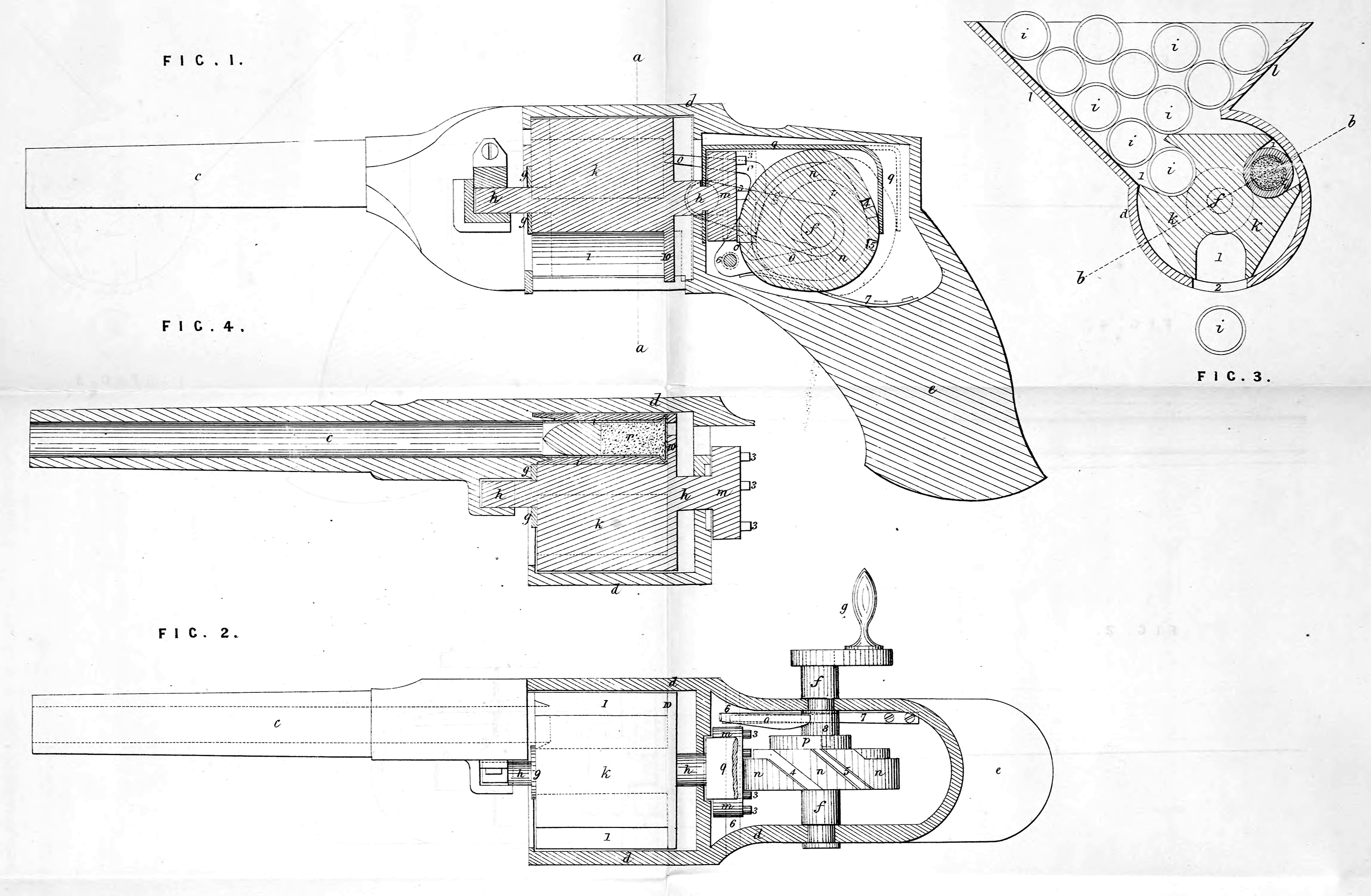
Fig. 1 is a vertical longitudinal section of my arm;
„ 2 is a plan, with the case over the works removed ;
„ 3 is a cross section at the line a, a; and –
„ 4 is a partial sectional plan at the line 6, b. Similar marks of reference denote the same parts.
The nature of my Invention consists, first, in the employment of a carrier, intermittently revolved by suitable automatic mechanism, and presenting a loaded chamber at the rear of the barrel, pausing while the charge is fired, then proceeding on by said mechanism, and presenting another chamber on the line of the barrel, the previous discharged chamber being allowed to drop out of the said revolving carrier.
Second, in combining with said revolving carrier a hopper, slide, or opening, so located on a plane parallel or nearly parallel to the axis of said revolving carrier, that the said chambers shall by their own gravity descend into the grooves provided in said revolving carrier, as such grooves are successively presented for the reception of said chambers.
Third, in combining with the said revolving carrier a shield or casing to retain the said chambers in the revolving carrier from the point at which they drop from the said hopper, slide, or opening until they have been fired; after which said chambers are allowed tp drop away by their own gravity.
Fourth, in the employment of a revolving cam in combination with said rotary carrier, said cam being so formed as to allow the necessary pause for the discharge of each chamber as brought opposite to the barrel; said cam also acting to hold the carrier and the chamber, so that the chamber is on the line of the barrel when fired.
Fifth, in the employment of automatic mechanism to press the chambers to the rear end of the barrel after being brought to line with the barrel by the aforesaid rotary carrier, so as to prevent the escape of gases, &c.
Sixth, in the combination with a detached section of a barrel or “ chamber of a metallic cartridge, so formed that the metallic case of the said cartridge enters the rear end of the barrel when pressed forward, as aforesaid.
Seventh, in constructing the mechanism that rotates the carrier in such a manner that a hammer is liberated to explode detonating powder and fire the piece at the time the said carrier is stationary, and then re-cock the hammer before the carrier commences again to move; the rotary automatic mechanism giving these relative movements to the hammer, and the carrier being unchecked in its revolution.
Eighth, in the mechanism employed for giving end motion to said carrier.
Ninth, in the means for moving the chambers with the carrier in its endwise action.
Tenth, in the mechanism for revolving the carrier.
In the Drawing c is a barrel of any desired size, either rifled or plain; this is to be connected with the mechanism of the gun by the metallic case d, which is formed of a size and shape adapted to the parts, and my arm may be provided with a stock e adapted to be grasped by the hand or placed against the shoulder, although my arm was originally designed for and especially adapted to a gun set on a rest or swivel, and guided with one hand, and revolved with the other; while the chambers are separately placed in by an attendant, or three or more attendants can be employed with such a gun, one to revolve the mechanism, a second to aim and guide the gun by hand or machinery, while one or more supply the same with the detached chambers; f is a short cross shaft, with a crank g at the end, or other mechanism, by which a rotary movement is given to said shaft /; h is the axis of the revolving carrier Jc9 and i, i, are the chambers; l is a slide opening or hopper so located that the chambers i, t, can be supplied through the same, and pass by their gravity into the grooves 1, 1, 1, of the rotary carrier h as the said carrier is revolved. The case d surrounding the rotary carrier acts as a shield to keep the chambers i, i, properly in the grooves 1,1, until after they have been fired, and an opening at 2 or the disconnecting of said shield allows the chambers to fall out after being fired.
In order to revolve the carrier fc I employ the disk m with the pins or projections 3, 3 $ there should be twice as many pins as there are grooves 1,1, in the rotary carrier; and n is a cam on the shaft/, that is the thickness corresponding to the distance between two of said pins 3, 3, except at a portion of its periphery, where diagonal grooves 4 and 5 are provided, which as the the cam n is revolved, take successively two of the said pins 3,3, passing them to the other side of the cam, hence turning the rotary carrier the amount necessary to bring another chamber i on line with the barrel, and the edges of this cam n and the respective pins 3, 3, one on each side, hold the said rotary carrier and the chamber i on line with the barrel with great precision ; and the revolution of the said cam n can be continuous although the carrier is by this mechanism allowed to pause while the piece is being fired.
In order to press the chambers i, i, up against the rear end of the barrel I also make use of the cam n, said cam being larger in diameter at the part which comes in contact with the disk m, after the carrier has been turned (by the grooves 4 and 5), thereby the said disk, carrier, and chambers are all pressed forward, and so held, to make a tight joint between the chamber i and the rear end of the barrel while being fired by the hammer o. This hammer o is on the axis or centre pin 6, and is fitted with a main spring 7, and the cam p on the shaft/acts on the tail 8 of the hammer to cock and keep the same cocked, except when the cam turns free from said tail 8, as shown by dotted lines in Fig. 1, when the piece is discharged by the hammer striking any suitable cap or detonating material.
In order to relieve the chambers i from the pressure against the rear end of the barrel I employ the bridle piece q that passes from the rear of the cam n to the front of the disk m, and the cam, in its revolution, relieving from said disk m and taking against this bridle piece q, draws the carrier and chambers back, as seen in dotted lines Fig. 1. A ring 9 rising slightly above the bottom of the grooves 1, 1, and attached to the said carrier k, taking against the front end of the chamber i ensures its retraction from the rear end of the barrel with the carrier. The form of chamber i may be that of a cavity, to receive powder and ball with a nipple for a cap, but I prefer the construction shown, in which a cylinder i, open at both ends, is employed to receive the cartridge r, formed with a metallic case containing. fulminating powder at the ring base, and containing the ball, with grease in the said case in front of the ball, as shown. This metallic case of the cartridge enters within the rear end of the barrel, and the rear end of the barrel sets into a conical recess in the forward end of the chamber i. With this character of cartridge it is necessary to have the rear end of the grooves 1, 1, closed by the recoil plate 10 ; that should be formed solid with the revolving carrier, only being provided with an opening for the passage of the pointed hammer o. The operation of my arm as a whole will be apparent from the foregoing and will not require repetition, and I need only remark, that the size and mode of forming and putting the respective parts together must depend upon the character and size of ball to be fired and the particular mode in which the piece is to be used in warfare.
Should a cartridge and chamber i be misplaced in the hopper Z, and so pass into the rotary carrier, it may become necessary to reverse the movement of the crank g and shaft/to torn the cartridge and chamber back out of the carrier, to effect which it is necessary that the hammer tail 8 should be depressed to clear the cam p. A small link may, for this purpose, depend from the hammer tail through an opening in the casing and be drawn down by hand. To move the chambers in the hopper and prevent them clogging I form the rotary carrier with flat surfaces between the grooves 1,1, which, in passing beneath the chambers, will give them a slight agitation.
What I claim as my Invention, and desire to secure by Letters Patent is,—
First, the employment of a grooved carrier (&) intermittently revolved by automatic mechanism, for presenting a chamber containing the charge to be fired to the rear end of the barrel, and holding the same in place while being fired, as set forth.
Second, I claim a hopper, slide, or opening (Z) combined with said revolving carrier, when such hopper, slide, or opening is so lacated that the chambers placed therein descend into the said carrier by gravity, as set forth.
Third, I claim a shield (cZ), in combination with said rotary carrier (&), and hopper, slide, or opening (Z), when said shield extends from the base of the hopper, slide, or opening (Z) to the point at which the chamber (t) is brought into line with the barrel for firing, as specified.
Fourth, I claim a revolving cam w, in combination with the rotary carrier k, for giving progressive motion to said carrier, and allowing a pause while the piece is being fired, as set forth.
Fifth, I claim the employment of automatic mechanism to press the chambers to the rear of the barrel, and then withdraw the same, in combination with the rotary carrier, also moved by automatic mechanism, so that the motions are in unison, as set forth.
Sixth, I claim the metallic case cartridge r, formed and acting as specified, in combination with the detached chambers (i) receiving the same, as specified.
Seventh, I claim the combination of the rotary carrier (&), cams n and p, and hammer (o), in the manner specified, the parts being so formed and timed that the motions are harmonious for the purposes and as set forth.
Eighth, I claim the bridle-piece (