
British 3452
LETTERS PATENT to William Clark, of 53, Chancery Lane, in the County of Middlesex, Engineer and Patent Agent, for the Invention of “ Improvements in Fire-arms.”—A communication from abroad by Philippe Antoine Mathieu, Proprietor, and Jules Felix Gevelot, Manufacturer, both of 29, Boulevart St. Martin, Paris.
Sealed the 5th June 1863, and dated the 26th December 1862.
PROVISIONAL SPECIFICATION left by the said William Clark at the Office of the Commissioners of Patents, with his Petition, on the 26th December 1862.
I, William Clark, of 53, Chancery Lane, in the County of Middlesex, Engineer and Patent Agent, do hereby declare the nature of the said Invention for “ Improvements in Fire-arms/’ tp b,e as follows :—
Guns are useful at certain distances when hunting wild animals and in warfare, while they are only useful at close quarters when furnished with a bayonet. The greater the danger the less is the value of the weapon, which is exactly the contrary of what should be the case. Mixed fire-arms are intended to increase the means of attack and defence in proportion as the danger increases. At the moment when it becomes necessary to use the bayonet the gun occupies the two hands of the huntsman or soldier.
According to this Invention I place a second weapon at their disposal at such a juncture without weakening the support of the gun with the left hand. The arrangement, which is very simple, is represented in the accompanying Drawing, which shows various methods of coupling a gun with a revolver.
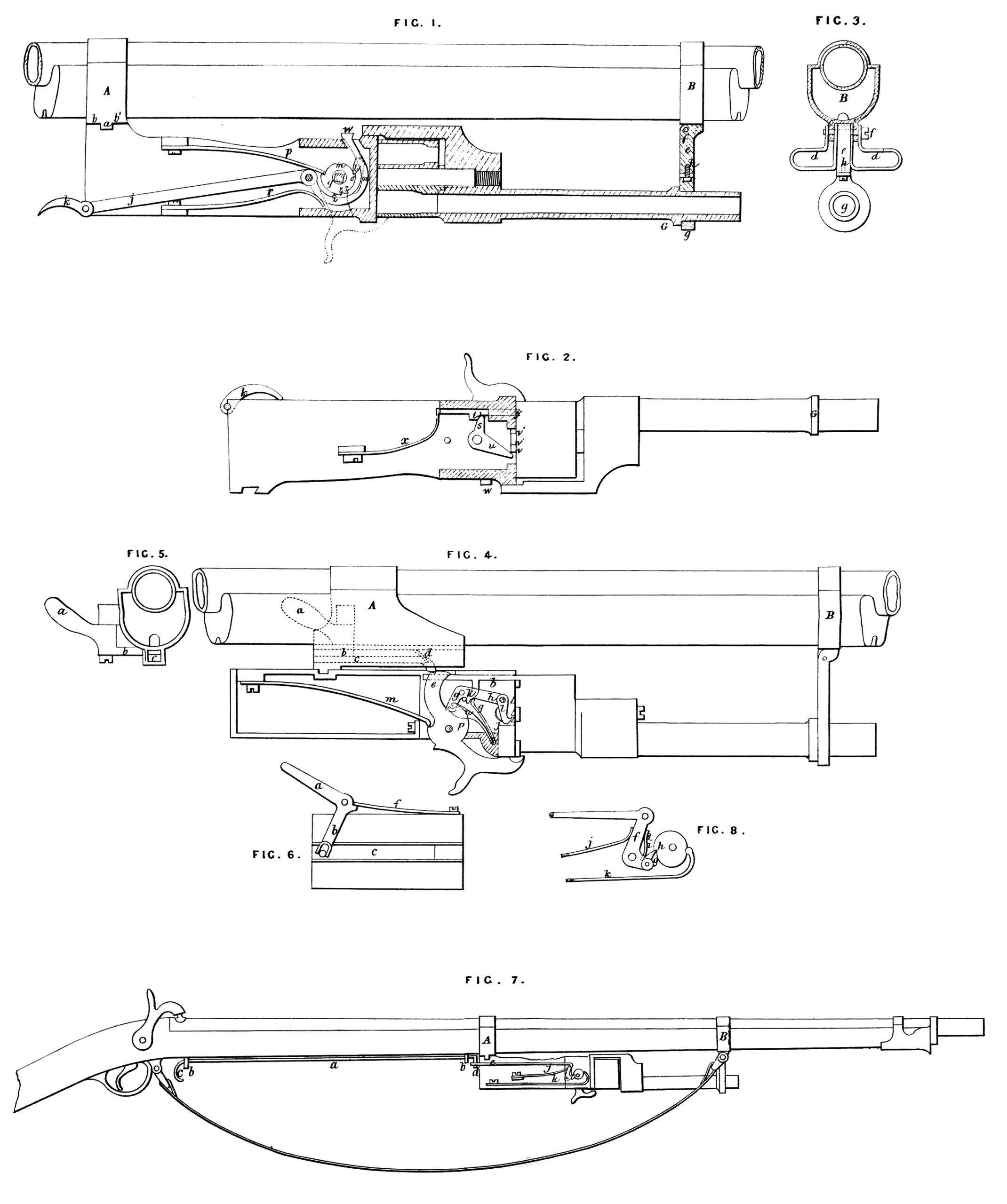
Fig. 1 shows part of the barrel and stock of a gun, to which is fitted a revolver, seen in longitudinal vertical section, with the front plate removed; Fig. 2 shows another view, the second plate of the revolver (seen detached) being removed; Fig. 3 shows a transverse section of a gun looking towards the revolver; Fig. 4 shows a portion of the barrel and stock of a gun having a revolver applied thereto, seen in side view, one of the plates being removed, the revolver being of different arrangement to that shown in Figs. 1, 2, and 3; Fig. 5 shows a transverse section of a gun behind the revolver ; Fig. 6 shows details to be herein-after described; Fig. 7 shows the barrel and part of the stock of a gun, to which is adapted a third arrangement of revolver ; Fig. 8 shows details to be herein-after described. This third arrangement is a modification of that represented at Figs. 1, 2, & 3. Figs. 1, 2, 3, 4, 5, 6, and 8, are drawn half the full size, while Fig. 7 is one-fifth of the full size.
Method op Fixing thb Revolver to the Gun.
The revolver is attached to the upper and lower bands A, B, Figs. 1,3, and 4, and the under part of band A has a dovetail a, and the two surfaces b, b\ to which is fitted the butt end of the revolver. The ordinary band carrying the buckle and sling is modified as shown in Fig. 3. It is furnished with two ears c, c1, to which are fitted two small buckles d, d1, for carrying the end of the sling, which is split for a length of about three inches, the space between being occupied by a strong bar et turning with buckles d, d1, on pin /. The bar e is terminated by a ring g of the same form as the barrel, either circular, polygonal, or of other form ; it is connected to bar e by a screw h9 on which it turns freely; when the revolver is not attached to the gun the bar e is folded under the barrel, where it is held by a spring.
Method op Fixing the Revolver.
The gun being held in the left hand and the butt of the revolver in the right, the end of the barrel is inserted in the ring g until the flange G is in contact therewith; the end of the butt is then brought towards the gun and engaged in dovetail a, the mortise being widened to facilitate its entrance; the bottom is also adjusted so as to lock the butt between the ring^ and the dovetail, while the heel i of bar e bears on band B and completes the locking. There now only remaius to maintain the revolver in position by applying a flexible pin to prevent the dovetail leaving the groove.
Various methods have been employed for firing the revolver, three of which I will proceed to describe.
First method.—A lever/, Figs. 1 and 2, projecting from the back end of the butt, may be easily moved by the fore or other finger of the left hand, or even by the palm of the hand if it is made of sufficient length. The extremity k of this lever may be folded back, and be entirely hidden, as shown at Fig. 2; when the revolver is detached in this manner there will be no fear of accident in pressing it by any cause. By acting on the end k of lever /, the pawH is held in contact with tumbler m, by the pressure of spring n; this pawl takes in tooth o, which it turns sufficiently to slip over it by reason of their respective inclination continually increasing; the spring p being then put in tension returns the tumbler to its original position. The hammer on the exterior is fixed to the tumbler m by the square part q\ and so participates in all its movements; and when the hammer is cocked the lever j is released; it is retured to its original position by means of spring r. It will be seen by referring to Fig. 2 that a double-armed lever of thin steel, which is slightly flexible, is fixed to the axis of the tumbler; it will be readily understood that in moving this lever * the bar t is forced backwards, and the breech chamber thus released may be raised by the arm u, which engages in catches v, v\ v2; on reaching a certaiu poiufc of its course, to be herein-after described, the lever $ escapes, and bar t being brought in contact with the breech chamber by spring.#, retains it in position by engaging in cavities v, v\ v*, made in the back end of the breech chamber.
Use of the Revolver separate from the Gun.
When the revolver is to be used separately the hammer acts without touching the lever j; at the moment the tooth z of the tumbler comes in contact with a tooth z1 on lever /, the bar t is held back, and the breech may be turned freely by band, and the chambers may be charged successively through an aperture made in the bottom of the breech chamber, or in other suitable manner; by continuing to pull the hammer lever u turns the breech chamber, bar t escapes, and catch & in its turn takes in tooth z\ The pistol being thus charged it is sufficient to slightly press the end w of levers* projecting underneath, in order to release the hammer and discharge the pistol.
Second method.—Figs. 4, 5, & 6 represent a revolver [requiring another mode of action. On the band A there is mounted a movable bent lever, the arm a of which is acted on by the thumb of the left hand, which transmits movement through arm b to catch c, sliding in a groove made in the band. This catch is pressed by spring d against tail piece e of the hammer, when the lever a is released the parts are returned to their original position by spring /. The catch c acts on the hammer by means of part ey and raises it thereby. The hammer in its movement acts on a bent lever g, the arm h of which turns the breech chamber by means of catch t, which is maintained in position by spring,/. In the space k of lever g a pin engages for advancing rod Z, in this manner the breech chamber being held between catch i and rod l cannot change its position. On arriving at a certain point of its course the catch c escapes, and the hammer is released and returns to its original position by spring m without however acting on lever g> which is maintained in position by means of spring n, which has a hook o at its end taking in a notch in lever g9 while at the moment when the hammer bears on the pin of the cartridge or on the nipple, and the tooth p raises spring w, lever g is then released and returns it its original position by means of spring q.
Third method.—In Figs. 7 and 8 there is shown a rod a sliding in guides b, b\ and terminated by a hook c in front of or inside the trigger guard of the gun. The other end d, which is bent at right angles, engages in a ring e in the butt of the revolver. By acting with the fore-finger of the right hand on the hook c, as on the tumbler of a gun-lock, the ring e is pulled, which transmits motion to a bent lever/ carrying a catch g. This catch engages in a tooth h in the tumbler, and acts in a similar manner to the catch l in Fig. 1. The small spring i holds the catch g in contact with the tumbler spring,/, returns lever /to its original position when released. The large spring k serves for acting on the hammer to produce the discharge. The remaining parts are the same as those above described with reference to Figs. 1, 2, and 3.
The Invention thus consists,—
1st, in connecting a revolver or other pistol to a single or double barrelled gun.
2ndly, in the arrangements herein described and represented for connecting said fire-arms.
3rdly, the three different methods described for firing the revolver, and which consists, 1st, by acting with the thumb of the left hand in the manner described; 2ndly, by acting on the end of the lever mounted behind the butt of the pistol; and, 3rdly, by means of a rod extending to the trigger guard, as also all the improvements in the parts of these three last arrangements.
SPECIFICATION in pursuance of the conditions of the Letters Patent, filed by the said William Clark in the Great Seal Patent Office on the 22nd June 1863.
TO ALL TO WHOM THESE PRESENTS SHALL COME, I, William Clark, of 53, Chancery Lane, in the County of Middlesex, Engineer and Patent Agent, send greeting.
WHEREAS Her most Excellent Majesty Queen Victoria, by Her Letters Patent, bearing date the Twenty-sixth day of December, in the year of our Lord One thousand eight hundred and. sixty-two, in the twenty-sixth year of Her reign, did, for Herself, Her heirs and successors, give and grant unto me, the said William Clark, Her special licence that I, the said William Clark, my executors, administrators, and assigns, or such others as I, the said William Clark, my executors, administrators, and assigns, should at any time agree with, and no others, from time to time and at all times thereafter during the term therein expressed, should and lawfully might make, use, exercise, and vend, within the United Kingdom of Great Britain and Ireland, the Channel Islands, and Isle of Man, an Invention for “ Improvements in Fire-arms,” a com11, to me from abroad, by Philippe Antoine Mathieu, Proprietor, and Jules Felix Gevelot, Manufacturer, both of 29, Boulevart St. Martin, Paris, upon the condition (amongst others) that I, the said William Clark, my executors or administrators, by an instrument in writing under my, or their, or one of their hands and seals, should particularly describe and ascertain the nature of the said Invention, and in what manner the same was to be performed, and cause the same to be filed in the Great Seal Patent Office within six calendar months next and immediately after the date of the said Letters Patent.
NOW KNOW YE, that I, the said William Clark, do hereby declare the nature of the said Invention, and in what manner the same is to be performed, to be particularly described and ascertained in and by the following statement, reference being had to the Sheet of Drawings hereunto annexed, and to the letters and figures marked thereon (that is to say):—
Guns are useful at certain distances when hunting wild animals and in warfare, while they are only useful at close quarters when furnished with a bayonet. The more imminent the danger the less is the value of the weapon, which is exactly the contrary of what should be the case. Mixed fire-arms are intended to increase the means of attack and defence in proportion as the danger increases. At a moment when it becomes necessary to use the bayonet the gun occupies the two hands of the huntsman or soldier.
According to this Invention I place a second weapon at their disposal at such a juncture without weakening the support of the gun with the left hand. The arrangement, which is very simple, is represented in the accompanying Drawing, which shows various methods of coupling a gun with a revolver.
Fig. 1 shows part of the barrel and stock of a gun, to which is fitted a revolver seen in longitudinal vertical section, with the front plate removed; Fig. 2 shows another view, the second plate of the revolver, seen detached, being removed ; Fig. 3 shows a transverse section of the gun looking towards the revolver; Fig. 4 shows a portion of the barrel and stock of a gun, having a revolver applied thereto, seen in side view, one of the plates being removed, the revolver being of different arrangement to that shown in Figs. 1, 2, and 3; Fig. 5 shows a transverse section of the gun behind the revolver; Fig. 6 shows details to be herein-after described; Fig. 7 shows the barrel and part of the stock of a gun, to which is adapted a third arrangement of revolver ; Fig. 8 shows details to be herein-after described. This third arrangement is a modification of that represented at Figs. 1, 2, and 3; Figs. 1, 2, 3, 4, 5, 6, and 8 are drawn to half the full size, while Fig. 7 is one-fifth the full size.
Method of Fixing the Revolvee to the Gun.
The revolver is attached to the upper and lower bands A, B, Figs. 1, 2, and 3, and the under part of band A has a dovetail a, and the two surfaces b, bl9 to which is fitted the butt end of the revolver. The ordinary band carrying the buckle and sling is modified as shown in Fig. 3. It is furnished with two ears c, c1, to which are fitted two small buckles d9 dl, for carrying the end of the sling, which is slit for a length of about three inches, the space between being occupied by a strong bar e turning with buckles d9