
US 457278
UNITED STATES PATENT OFFICE.
ADAMANTIUS CORAY HOUSTON, OF PICKAWAY, WEST VIRGINIA.
LOCK MECHANISM FOR REVOLVERS.
SPECIFICATION forming part of Letters Patent No. 457,278, dated August 4, 1891.
Application filed October 9, 1890. Serial No. 367,526, (No model.)
To all whom it may concern:
Be it known that I, ADAMANTIUS CORAY HOUSTON, of Pickaway, in the county of Monroe and State of West Virginia, have invented new and useful Improvements in Fire-Arms, of which the following is a full, clear, and exact description.
The object of the invention is to provide certain new and useful improvements in firearms, whereby the cylinder is rotated and the firing-pin is moved by revolving the trigger.
The invention consists of a trigger mounted to turn and to control the movements of the firing-pin and cylinder.
The invention also consists of certain parts and details and combinations of parts, as will be hereinafter fully described, and then pointed out in the claims.
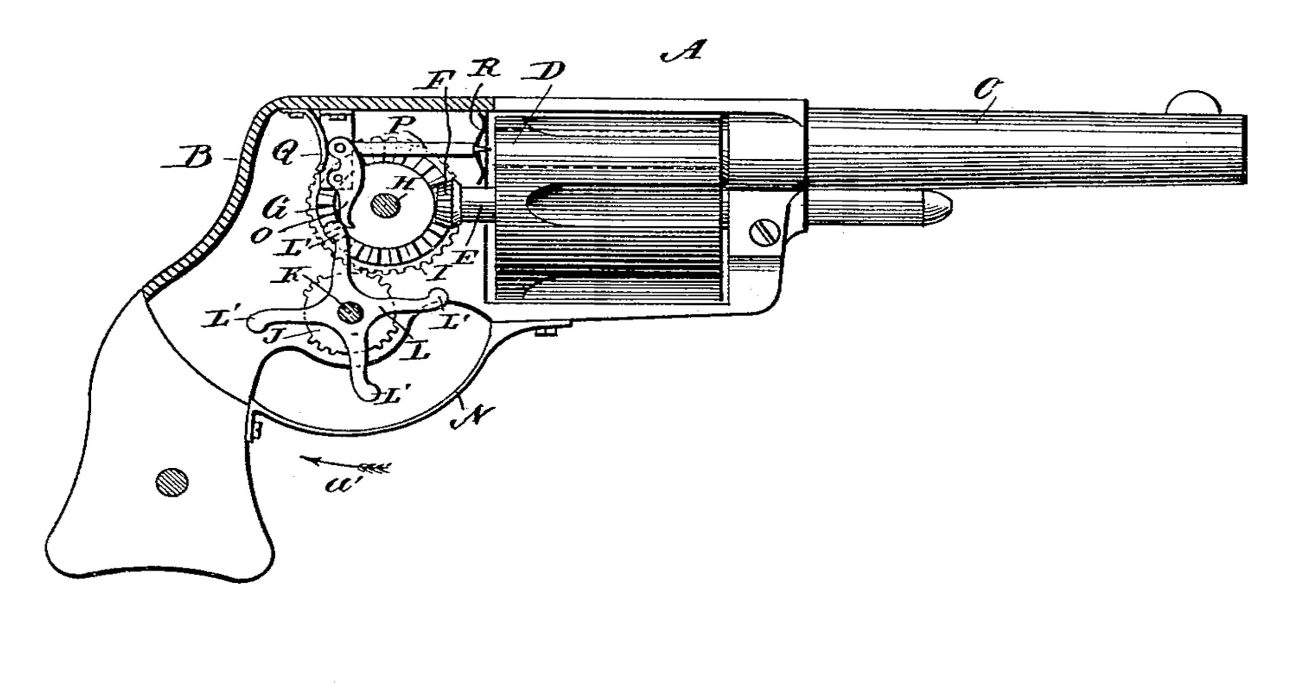
Reference is to be had to the accompanying drawing, forming a part of this specification, in which the figure is a side elevation of the improvement as applied to a revolver, parts being in section.
The revolver A, on which the improvements are applied, is provided with a suitable casing B, on which is secured the barrel C, adapted to connect with the chambers of the cylinder D, secured on an axle E, mounted to turn in suitable bearings in the casing B. On the inner end of the axle E is secured bevel-pinion F, meshing into a bevel gear-wheel G, secured on a shaft H, extending transversely and mounted to turn in suitable bearings in the sides of the easing B. On the rim of the bevel gear-wheel G is formed a spur-wheel I, in mesh with the sectional gear-wheel J, secured on a shaft K, extending transversely below the shaft H, and also mounted to turn in suitable bearings in the casing B. On the shaft K is secured a trigger L, formed with a number of arms L’, adapted to extend through the bottom of the casing and protected, where extending, by the usual guard N.
The arms L’ of the trigger L are adapted to engage alternately the lower end of a lever O, fulcrumed in the casing and pivotally connected at its upper end with the firing-pin P, adapted to fire the cartridge in the uppermost chamber of the cylinder D. A strong spring Q presses against the upper end of the lever O, so as to force the firing-pin P forward when the lever O is released from the respective arm L’ of the trigger L. A spring R is connected with the free end of the firing-pin P, which serves to hold the latter away from the face of the cylinder D to permit the revolving of the latter.
The operation is as follows: When the several parts are in position shown in the drawing and the cylinder D is filled with cartridges and the operator desires to discharge the fire-arm, then he pulls on the projecting arm of the trigger L in the direction of the arrow a’, so that the shaft K rotates and by the sectional gear-wheel J imparts a rotary motion to the gear-wheel I, which, by the bevel gear-wheel G, meshing into the pinion F, revolves the axle E, so that the next chamber in the cylinder D moves into line with the firing-pin P. By this time the section of teeth on the gear-wheel J has run out of mesh with the teeth on the gear-wheel I, so that the latter remains stationary at the further revolving of the trigger L. The cylinder D consequently remains stationary. The trigger L on the further revolving, by pulling on the projecting arm, causes its uppermost arm to move in contact with the lower end of the lever O to swing the same, so that the upper end moves rearward against the heavy spring Q, at the same time drawing the firing-pin P rearward. The arm L’ of the trigger L finally passes off of the lower end of the lever O, so that the heavy spring Q suddenly forces the firing-pin P forward, so that the point of the latter strikes the cartridge and fires the same. The firing-pin P is returned to its former position after the firing by the spring R. By this time the next arm L’ of the trigger L has moved into the space above the guard N, and by the operator pulling on this arm in the direction of the arrow a’ brings the next section of teeth on the gear-wheel J in mesh with the gear-wheel I, so that the latter is again rotated. The cylinder D is shifted to bring the next filled chamber in line with the barrel and the firing-pin P. The above described operation is then repeated. If necessary, a suitable spring or other means may be employed to retain the cylinder D in a firm position during the movement of the firing-pin P, as above described, so as to prevent accidental displacement of the uppermost chamber of the cylinder with the barrel C.
I do not limit myself to the detailed construction shown and described, as other suitable means may be employed to actuate the cylinder and the firing-pin from the revoluble trigger.
Having thus fully described my invention, I claim as new and desire to secure by Letters Patent—
1. The combination, in a fire-arm, with the frame, the rotary cylinder, and the firing-pin or striker provided with a pivoted lever, of a rotary armed trigger journaled in the frame and into the path of the arms of which said lever projects to be operated by the arms successively, the lowermost arm projecting through the easing for action by the operator’s finger, a mutilated gear connected to said rotary trigger, and gearing operated thereby and connected to the cylinder, substantially as set forth.
2. In a fire-arm, the combination, with a firing-pin, of a spring-pressed lever pivotally connected with the said firing-pin, and a trigger mounted to turn and provided with a series of arms adapted to alternately engage the said lever, substantially as shown and described.
3. In a fire-arm, the combination, with a firing-pin, of a spring-pressed lever pivotally connected with the said firing-pin, a trigger mounted to turn and provided with a series of arms adapted to alternately engage the said lever, and a spring connected with the said firing-pin to return the same to its normal position, substantially as shown and described.
4. In a fire-arm, the combination, with a cylinder mounted to turn, of a pinion secured on the axle of the said cylinder, a gear-wheel in mesh with the said pinion, a second gearwheel held on the shaft of the first-named gear-wheel, and a sectional gear-wheel adapted to mesh into the second-named gearwheel, and a trigger provided with arms and secured on the shaft of the said sectional
gear-wheel, substantially as shown and described.
ADAMANTIUS CORAY HOUSTON.
Witnesses:
S. A. HOUSTON,
J. B. HOUSTON.