
US 456179
UNITED STATES PATENT OFFICE
JOSEPH H. WESSON, OF SPRINGFIELD, MASSACHUSETTS.
BARREL-CATCH for REVOLVERS.
SPECIFICATION forming part of Letters Patent No. 456, 179, dated July 21, 1891.
Application filed December 4, 1890. Serial No. 373, 521. (No model.)
To all whom it may concern:
Be it known that I, JOSEPH H. WESSON, a citizen of the United States, residing at Springfield, in the county of Hampden and State of Massachusetts, have invented new and useful Improvements in Revolving Fire- Arms, of which the following is a specification.
This invention relates to revolving firearms and pertains to improved barrel-catch mechanism therefor having connected therewith improved means for operating in connection with the firing mechanism of the arm, whereby it is made impossible to operate said firing mechanism and discharge the arm before the barrel-strap is fully and completely engaged by the barrel-catch devices on the frame of the arm back of the cylinder; and the invention consists in the construction and arrangement of said barrel-catch mechanism, all as hereinafter fully described, and pointed out in the claims.
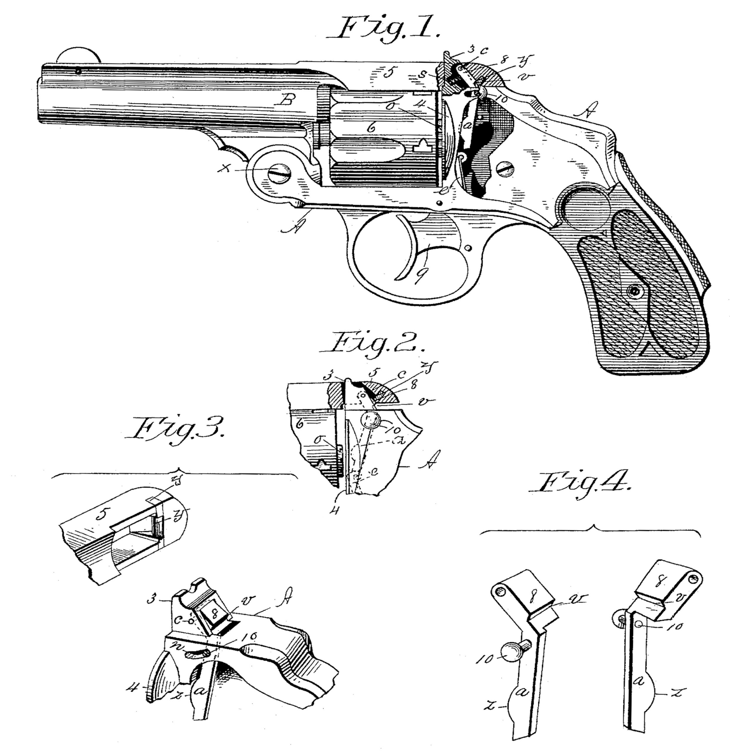
In the drawings, forming part of this specification, Figure 1 is a side elevation of a revolving fire-arm embodying my invention, this figure showing the side plate partly broken away, the rear part of the barrel-strap and the catch-post in section and the barrel-catch and safety mechanism in side elevation, this figure showing the barrel-catch mechanism fully engaged with the barrel-strap. Fig. 2 is a side view of the rear end of the barrel-strap and of the cylinder and of the adjoining part of the frame of the arm, the barrel-strap being shown partly in section, this figure illustrating the position of the barrel-catch mechanism just before it engages the barrel-strap. Fig. 3 is a perspective view of the rear under side portion of the barrel-strap of the arm and of that part of the frame of the arm against which the barrel-strap Swings, and of the catch-post and barrel-catch devices connected thereto. Fig. 4 is a perspective view of the barrel-catch and its safety-arm, showing the same in two positions.
In the drawings, A is the frame of the arm having the usual catch-post 3 and recoil-plate 4 thereon. B is the barrel pivoted to the frame A at x, and having the barrel-strap 6 thereon, which extends over the cylinder 6, and is perforated to receive the end of said post and to engage with a catch thereon. The cylinder 6 occupies the usual position at the rear of the barrel, and, when in firing position, between the latter and said recoil-plate. The catch 8 is pivoted in a recess in said catch-post, as shown, and has thereon a pending arm a. The said catch 8 has a vibratory motion on its pivot c, whereby its said pending arm has its lower end swung over and away from the upper end of the cylinder-turning pawl e, this pawl being pivoted by its lower end in the usual manner to the rear part of the trigger and having its upper end protruding through a slot in the recoil-plate to engage with the ratchet o on the rear end of the cylinder, thereby effecting the rotation of the latter when the trigger 9 is operated to fire the arm. Said pending arm a is provided with a curved projection z on the edge thereof adjoining the rear side of the recoil-plate 4, to the end that the rear edge of the upper end of the pawl e may strike said projection z when it moves up between the arm c and the recoil-plate to turn the cylinder 6, and thereby at the instant of firing the arm press the latter rearward and force and hold the shoulder v on the catch 8 at this instant in positive engagement with the shoulder-piece y in the barrel-strap and render any disengagement of the catch devices through the sudden shock of firing the arm impossible. The said barrel-catch 8 has a hardened shoulder v on its rear face, which engages with a similar shoulder on the adjoining side of the barrel-strap 5, consisting of a hardened shoulder-piece y, which is rigidly fixed in the strap 5 in the position shown in Figs. 1, 2, and 3. The said shoulder parts are hardened, as described, to obviate any wear of their surfaces which would otherwise ensue from their frequent abrading contact, thereby insuring, as far as possible, the absolute contact of the rear end of the barrel-strap with that part of the frame of the arm surrounding the catch-post when the barrel is brought to firing position and the catch is engaged with said strap to properly lock the parts. A coil or other suitable spring s is placed in said recess in the catch-post back of the catch 8, which operates to swing the latter against the adjoining part of the barrel-strap to engage the latter and the catch, and at the Same time to swing the lower end of the safety-arm o sufficiently away to the rearward from the upper end of the pawl e to permit the latter and the trigger 9 to be operated. When the arm is in firing position, as shown in Fig. 1, the rear end of the barrel-strap 5 entirely covers the barrel-catch 8, and therefore, to provide suitable means for operating the same to swing it forward out of engagement with the barrel-strap, so that the barrel may be swung on its pivot to manipulate the cylinder for loading the same, a pin 10 is passed through a curved-slot n in the side of the frame and screwed or otherwise suitably connected with the edge of the barrel catch or its arm a, against the side of which the thumb is pressed to swing the barrel-catch as aforesaid and disengage it from the barrel-strap. The said barrel-catch 8 may be used simply as such and be operated by said pin 10; and, if desired, the said safety arm o may be omitted from the catch.
The operation of the within described improvements is as follows: After firing the arm the barrel-catch, the safety-arm o thereon, the pawl e, and the trigger 9 occupy the position shown in Fig. 1. Should the cylinder now require to be loaded with cartridges, the barrel-catch is swung forward out of engagement with the adjoining side of the barrel-strap by pressing, as aforesaid, against the rear side of the pin 10 on the side of the arms. The movement of the barrel-catch so effected brings said catch and the safety-arm o thereon to the positions substantially illustrated in Fig. 2, hereby the shoulder v of said catch is moved off from the shoulder y on the barrel-strap 5, thereby disengaging the latter from the catch and causing the safety-arm o to swing to the position indicated by dotted lines in Fig. 2—that is to say, bringing the lower end of said arm o directly over the upper end of the pawl e. With the catch in this last-named position the barrel-strap is disengaged therefrom, leaving the barrel and cylinder free to be swung to a position which permits of loading the cylinder. After loading the cylinder and attempting to swing the barrel back to the position shown in Fig. 1, if the operator fails to bring the end of the barrel-strap 5 completely against the surface of the frame surrounding the catch-post 3 the shoulder-piece y (shown as engaging the side of the catch adjoining its shoulder v) will continue so to engage same and hold the catch and its safety-arm in the position shown in Fig. 2, the lower end of said arm being thereby held directly over the end of the pawl e and preventing the trigger 9 from being pulled, and consequently preventing the arm from being fired until there is a perfect engagement of the barrel-catch and barrel-strap, as shown in Fig. 1.
Thus it is seen that the above-described safety-catch devices render it impossible to inadvertently discharge the arm until the barrel-strap is rigidly locked to the frame at the rear of the cylinder, or that the catch devices can become disengaged at the moment of firing the arm. Without such safety devices, whereby the operation of the lock mechanism is prevented for the purpose aforesaid, the careless use of the arm or a thick-headed cartridge may result in a defective engagement of the barrel-strap with the frame A back of the cylinder, and consequently lead to serious accidents should the arm be fired without such perfect engagement of parts as is above referred to.
Having fully described my invention, what is claim, and desire to secure by Letters Patent, is—
1. A revolving fire-arm having a catch-post thereon at the rear of the cylinder; in which is a catch-recess, the barrel-strap, perforated to receive said post, the trigger; the cylinder-pawl pivotally attached to said trigger, a catch pivotally hung in said recess to engage with said strap, having an arm thereon, the end of which moves over and from the end of said pawl coincidently with the vibratory motions of said catch, and a spring to move the catch against said strap, combined and operating substantially as set forth.
2. In a revolving fire-arm, a catch-post thereon at the rear of the cylinder; in which is a recess to receive a barrel-strap catch; the barrel-strap perforated to receive said post; a catch pivotally hung in said recess, a catch-operating pin on said catch extending laterally through a slot in the side of the arm, and a spring to move the catch against said strap, combined and operating substantially as set forth.
3. In a revolving fire-arm, a catch-post thereon at the rear of the cylinder, in which is a recess to receive a barrel-strap catch, the barrel-strap, having a perforation to receive said post, on one side of which is a hardened shoulder-piece y, a catch pivotally hung in said recess, having a hardened shoulder to engage with said shoulder-piece, a catch-operating pin on said catch extending laterally through a slot in the side of the arm,and a spring to move said catch and effect the engagement of said shoulders, combined and operating substantially as set forth.
4. A revolving fire-arm having a catch-post thereon at the rear of the cylinder, in which is a catch-recess, the barrel-strap perforated to receive said post, the trigger, the cylinder-pawl pivotally attached to said trigger; a catch pivotally hung in said recess to engage with said strap, having a pending arm thereon; between which and the recoil-plate said pawl moves when the trigger is pulled, thereby preventing any movement of said arm and catch when the fire-arm is discharged, combined and operating substantially as set forth.
JOSEPH H. WESSON.
Witnesses:
G. M. CHAMBERLAIN,
H. A. CHAPIN.