
US 453421
UNITED STATES PATENT OFFICE.
HOMER M. CALDWELL, OF WORCESTER, MASSACHUSETTS, ASSIGNOR TO
SULLIVAN FOREHAND, OF SAME PLACE.
REVOLVER.
SPECIFICATION forming part of Letters Patent No. 453,421, dated June 2, 1891.
Application filed January 5, 1891, Serial No. 376,762. (No model.)
To all whom it may concern:
Be it known that I, HOMER M. CALDWELL, a citizen cf the United States, residing at Worcester, in the county of Worcester and State of Massachusetts, have invented a new and useful Improvement in Revolvers, of which the following, together with the accompanying drawings, is a specification sufficiently full, clear, and exact to enable persons skilled in the art to which this invention appertains to make and use the same.
The object of my present invention is to afford a simple, desirable, and practically efficient construction in certain parts of the mechanism hereinafter particularly specified, to render the arm more convenient and serviceable, and to facilitate economy of manufacture.
The particular subject-matter claimed is definitely pointed out in the following description and summary.
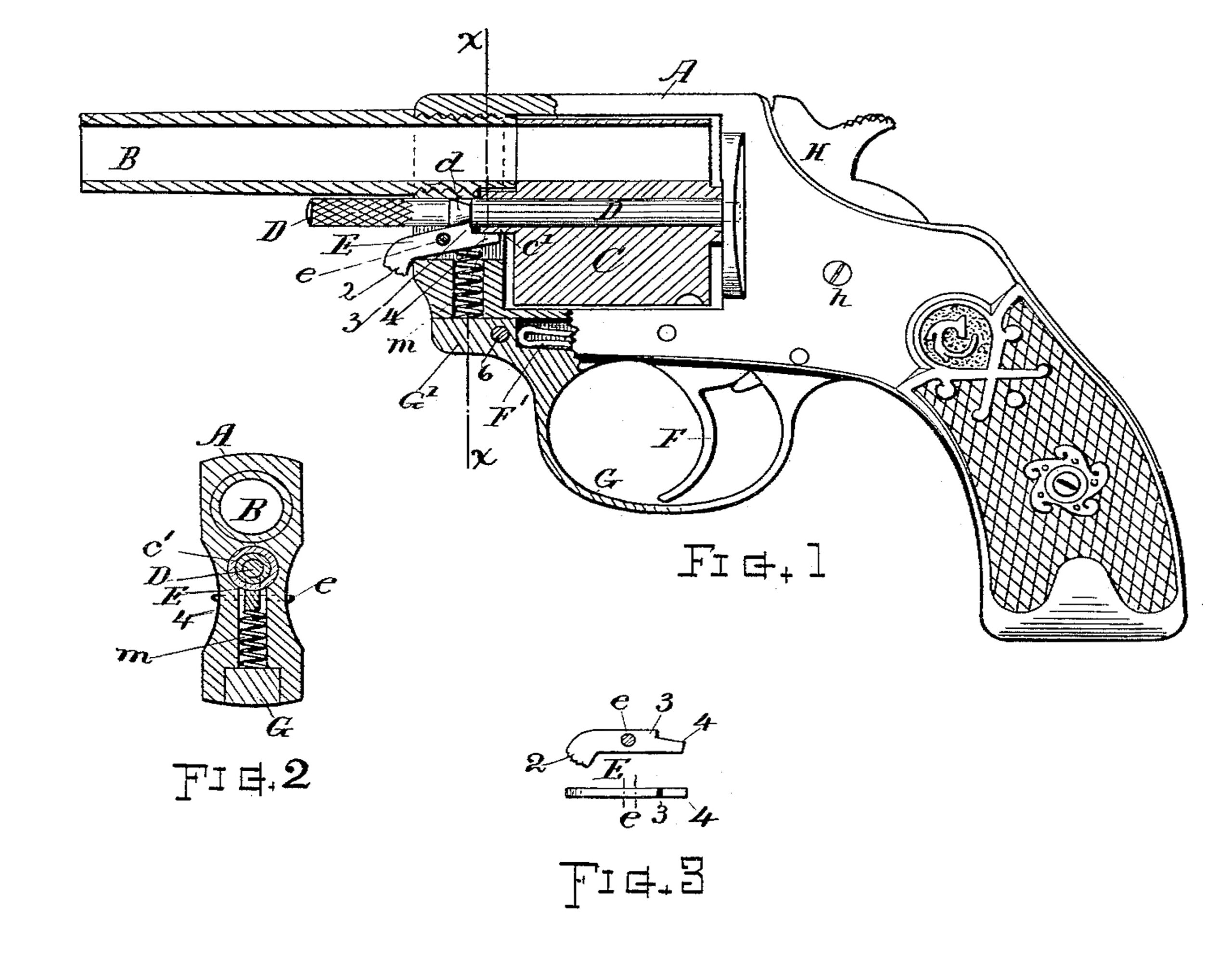
In the drawings, Figure 1 is a part side and part vertical longitudinal sectional view of a revolver, illustrating the features of my invention. Fig. 2 is a transverse section at line x x on Fig. 1. Fig. 3 shows in side and top views the center-pin catch.
Referring to parts, A denotes the frame; B, the barrel; C, the cylinder; D,the removable center-pin on which the cylinder rotates; E, the center-pin catch; F, the trigger; F’, the trigger-spring; G, the guard; H, the hammer pivoted at h, which parts are relatively disposed and combined substantially, as illustrated.
In general structure, except in the particulars and improvements hereinafter specified, the parts may be of well-known form and arrangement.
The center-pin D, which is of suitable form, is provided with the usual notch or shoulder d, and is inserted through the frame and central bore of the cylinder in well-known manner. The center-pin catch E is fitted within a ; longitudinal recess formed in the frame below the center-pin, and is fulcrumed on the transverse pin e for tilting action. Its forward end 2 is made in usual form with a protruding roughened surface to receive pressure of the thumb for disengaging the catch. Said catch is pressed upward by means of a spring m, disposed beneath its inner end, and is furnished with a point or angle 3, that engages the notch or shoulder d when the center-pin is in normal position.
A feature of my invention consists in the extension of the rear end of this center-pin catch E beyond the latching-point 3, as at 4, to form a bearing or friction surface, and arranging the same in such manner that the extended end 4 will bear against the collar or hub c’ on the forward end of the cylinder C, and there serve as a presser or friction-brake to prevent too free rotation of the cylinder about the center-pin and to obviate liability of the cylinder turning out of place with the
backward movement of the hand or actuating-pawl I. The spring m is of coiled wire and simply dropped into the drill-hole in the fore-end of the frame beneath the catch. Said spring is confined by the forward end G’ of the guard G, which is fitted into the frame and secured by the pin e, the spring being thus retained in place without special fastenings and in a very simple and convenient manner.
I claim as my invention herein to be secured by Letters Patent—
1. The center-pin catch having the extension 4, that bears against the hub or collar C’ of the cylinder, and the point 3 for engagement with the shoulder or notch d on the center-pin, in combination with the frame, the cylinder, and the center-pin, substantially as for the purpose set forth.
2. The combination, with the frame A, the cylinder C, and the notched center-pin D, of the center-pin catch E, fitted in the recess at the fore-end of the frame and fulcrumed at e for tilting action, said catch having the thumb projection 2, the engaging-point 3, and the extended end 4, that serves as a friction-brake against the cylinder-collar C’, the coiled spring m, disposed in a drill-hole beneath said catch, and the guard G, having its fore-end fitted into the frame and confining said spring, substantially as set forth.
Witness my hand this 1st day of January, A. D. 1891.
HOMER M. CALDWELL.
Witnesses:
CHAS. H. BURLEIGH,
ELLA P. BLENUS.